

Flow measurement device and system with anti-blocking function
A flow measurement device and function technology, applied in the field of flow measurement devices and systems with anti-blocking function, can solve the problems of unstable differential pressure signal, easy accumulation and scaling, etc., to achieve stable flow coefficient, strong impact ability, and reduced The effect of permanent pressure loss
- Summary
- Abstract
- Description
- Claims
- Application Information
AI Technical Summary
Problems solved by technology
Method used
Image

Examples
Embodiment 1
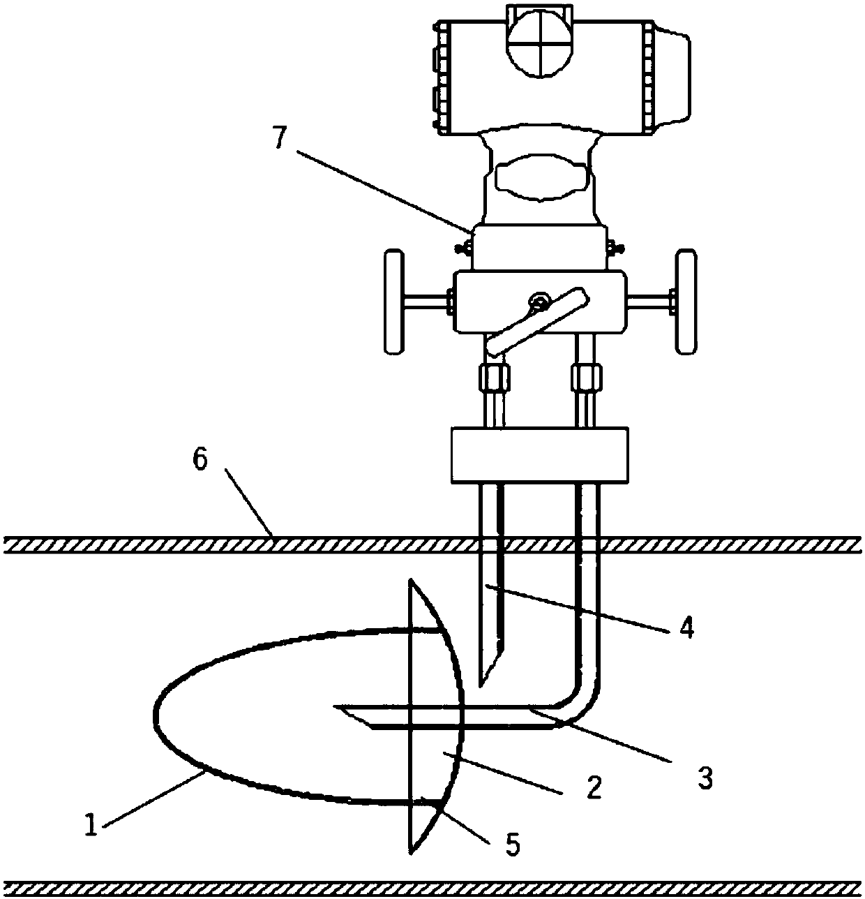
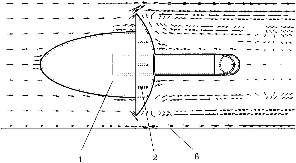
[0075] figure 1 A schematic structural view showing a flow measuring device with an anti-blocking function according to a first exemplary embodiment of the present invention, figure 2 A fluid state diagram is shown when the flow measurement device with anti-blocking function according to the first exemplary embodiment of the present invention is in operation.
[0076] Such as figure 1 with 2 As shown, flow measurement devices with anti-blocking function include:
[0077] Pressure guiding plate 2;
[0078] The rectifying dust cover 1, the rectifying dust cover 1 is arranged on one side of the pressure guide plate 2, and the rectifying dust cover 1 and the pressure guiding plate 2 surround to form a cavity communicating with the outside of the rectifying dust cover 1;
[0079] High pressure pressure induction pipe 3, one end of the high pressure pressure induction pipe 3 is arranged in the cavity;
[0080] Low-pressure pressure-inducing pipe 4, one end of low-pressure-indu...
Embodiment 2 4
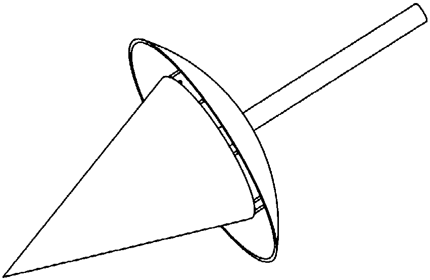
[0085] The difference between the flow measurement device with anti-blocking function according to the second, third and fourth exemplary embodiments of the present invention and the first exemplary embodiment lies in the shape of the rectifying dust cover. Figure 3a , Figure 3b with Figure 3c The perspective views of the rectifying dust cover of the flow measuring device with anti-blocking function according to the second, third and fourth exemplary embodiments of the present invention are respectively shown. Such as Figure 3a , Figure 3b with Figure 3c As shown, the rectifying dust cover can be in the shape of a cone, a pyramid or a curved surface cone, and these shapes are all conducive to reducing the resistance of the rectifying dust cover to the fluid.
Embodiment 5 9
[0087] The difference between the flow measurement devices with anti-blocking function according to the fifth to ninth exemplary embodiments of the present invention and the first exemplary embodiment lies in the shape of the pressure guiding plate. Figure 4a , Figure 4b , Figure 4c , Figure 4d with Figure 4e The perspective views of the pressure guide plates of the flow measurement devices with anti-blocking function according to the fifth to ninth exemplary embodiments of the present invention are respectively shown. exist Figure 4a In the shown embodiment, the pressure guiding plate is a curved surface; Figure 4b In the shown embodiment, the pressure guiding plate is a disc; Figure 4c In the shown embodiment, the pressure guide plate is in the shape of a square tray; Figure 4d In the shown embodiment, the upper half of the pressure guiding plate is a curved surface, and the lower half is rectangular; Figure 4e In the illustrated embodiment, the pressure gui...
PUM
 Abstract
Description
Claims
Application Information