Magnetic induction particle detection device and concentration detection method

A particle detection and concentration detection technology, applied in measurement devices, particle suspension analysis, particle and sedimentation analysis, etc., can solve problems such as difficulty in accurately detecting the concentration of metal particles in fluids, unfavorable design, preparation, installation and use, and affecting detection results.

Active Publication Date: 2018-04-13
FATRI UNITED TESTING & CONTROL QUANZHOU TECH CO LTD
View PDF10 Cites 14 Cited by
  • Summary
  • Abstract
  • Description
  • Claims
  • Application Information

AI Technical Summary

Problems solved by technology

[0004] (1) In order to establish the magnetic field balance and induce the magnetic field signal of metal particles, two reverse excitation coils and one induction coil are required, and the design makes the sensor length longer, which is not conducive to actual design, preparation, installation and use;
[0005] (2) Only one magnetic induction coil is used. When electromagnetic induction is used for magnetic field balance, the magnetic field attenuation outside the excitation coil (excitation coi

Method used


Image

  • Magnetic induction particle detection device and concentration detection method
  • Magnetic induction particle detection device and concentration detection method
  • Magnetic induction particle detection device and concentration detection method

Examples


Embodiment 1

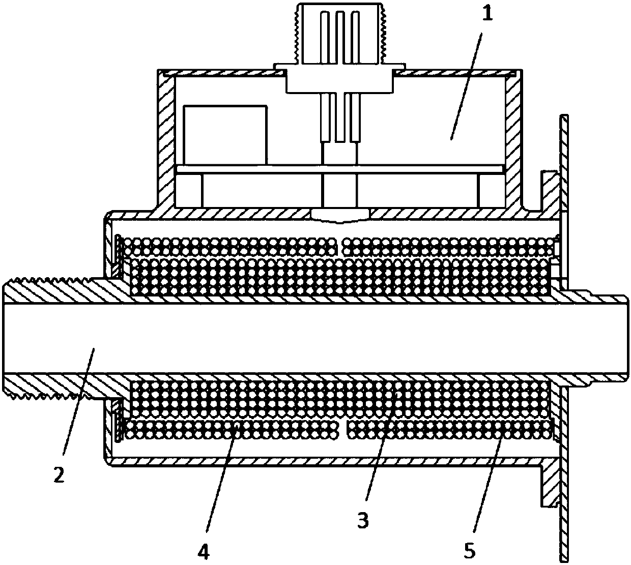
[0073] Embodiment 1 (magnetic induction particle detection device)

[0074] Such as figure 1 As shown, it is a schematic cross-sectional structure diagram of the first preferred embodiment of the magnetic induction particle detection device of the present invention; the detection device includes a signal detection system 1, a detection pipeline 2, an excitation coil 3, and two induction coils (respectively the first Induction coil 4 and second induction coil 5), the excitation coil is connected with the signal processing system and wound on the detection pipeline; the induction coils are all connected with the signal processing system, sequentially and opposite to each other wound on the excitation coil.

[0075] The above is one of the preferred implementations of the technical solution. This basic implementation has the following

[0076] Beneficial effect:

[0077] (1) The setting method of the excitation coil and the induction coil wound outside the device can achieve ...

Embodiment 2

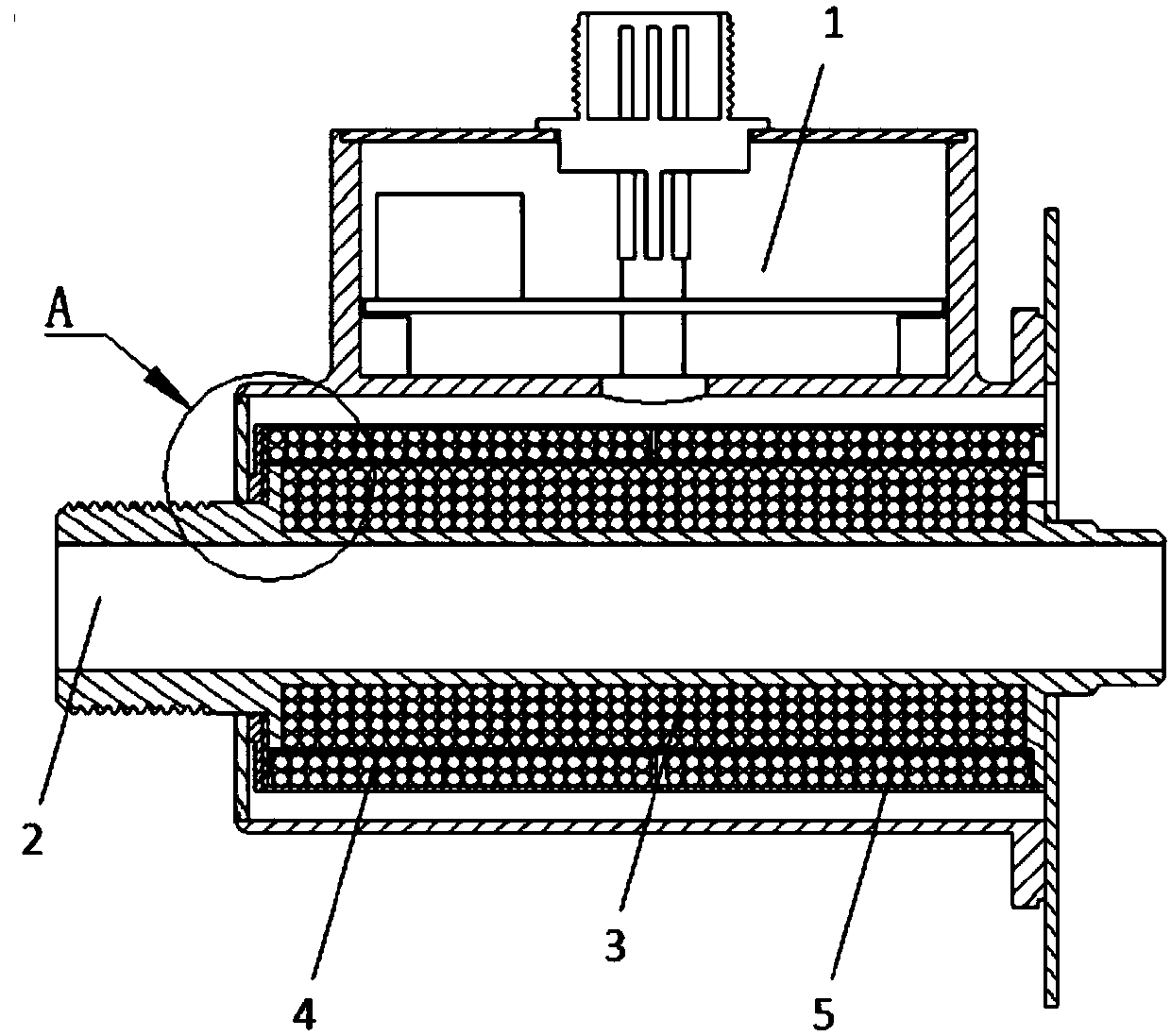
[0084] Embodiment 2 (magnetic induction particle detection device)

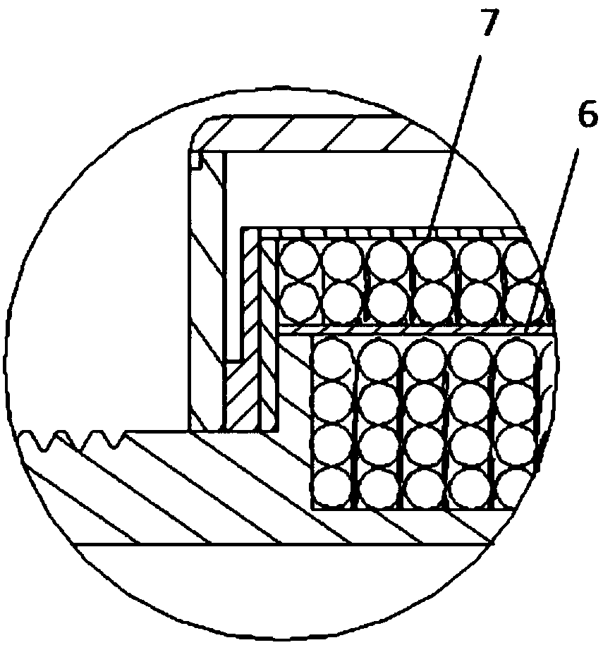
[0085] Such as figure 2 Shown is a schematic structural diagram of the second preferred embodiment of the magnetic induction particle detection device of the present invention; the difference between this embodiment and the above-mentioned embodiment 1 is that: image 3 As shown, a spacer sleeve 6 is also arranged between the excitation coil and the induction coil in the detection device, that is, the excitation coil is covered with a spacer sleeve, and the induction coil is wound on the on the spacer sleeve. And, a shielding ring 7 is provided outside the induction coil.

[0086] The above two technical solutions can be implemented together, or only one can be implemented, depending on the needs. In this embodiment, both solutions are implemented, that is, a spacer ring sleeve and a shielding ring are provided, which is a more preferred implementation manner.

[0087] There is a spacer sleeve, on the on...

Embodiment 3

[0097] Embodiment 3 (concentration detection method utilizing magnetic induction particle detection device)

[0098] This embodiment provides a detection method using the magnetic induction particle detection device of the above embodiment, including the following steps:

[0099] S1: Obtain the output signal of the signal detection system to obtain the change of the voltage amplitude;

[0100] S2: Detect the concentration of metal particles according to the obtained voltage amplitude change;

[0101] Wherein, the change of the voltage amplitude includes the change of the voltage amplitude and time, that is, the relationship between the change of the voltage amplitude and the time, for example, the voltage amplitude at a certain point and the time at which it is located.

[0102] In one preferred embodiment, detecting the concentration of metal particles comprises the following steps:

[0103] Obtain the flow velocity v of the metal particles passing through the induction coi...


PUM


Abstract

The invention provides a magnetic induction particle detection device and a concentration detection method. The detection device comprises a signal detection system, a detection pipeline, an excitation coil and a positive even number of induction coils, wherein the excitation coil is connected with a signal processing system and wound on the detection pipeline; and the induction coils are connected with the signal processing system and are sequentially and reversely wound on the excitation coil. The device can facilitate preparation and installation and can improve the detection precision. Themethod comprises the following steps: S1, obtaining an output signal of the signal detection system to obtain a voltage amplitude change condition; and S2, detecting the metal particle concentrationaccording to the obtained voltage amplitude change condition. Through the method, the accuracy of calculation can be improved.

Description

technical field [0001] The present invention relates to the field of detection equipment, in particular to a magnetic induction particle detection device, and further, to a method for using the device to detect concentration. Background technique [0002] At present, there are many methods used to detect metal particles, among which the detection of metal particles using the principle of electromagnetic induction is a more commonly used method. Specifically, the usual device for detecting metal particles using the principle of electromagnetic induction often uses two oppositely wound excitation coils as the excitation source to generate two magnetic fields with the same strength and opposite directions. The net magnetic field is zero; an induction coil for inductive magnetic field change is wound in the middle to sense the magnetic field disturbance caused by metal particles. [0003] Although this device can realize the electromagnetic detection of metal particles, the dev...

Claims


Application Information

Patent Timeline
IPC IPC(8): G01N15/06
CPCG01N15/0656G01N2015/0687G01N2015/0053G01N33/2858G01N2015/0003G01N2015/1075
Inventor 聂泳忠张中萍
Owner FATRI UNITED TESTING & CONTROL QUANZHOU TECH CO LTD
Why Eureka
Try Eureka