A circuit, method and device for digitizing array radar signals
An array radar and signal technology, applied in the field of electronic information, can solve the problem that the array radar signal is difficult to meet the high sampling rate and high conversion accuracy at the same time, and achieve the effect of improving the sampling speed and conversion accuracy, improving the sampling depth and high conversion accuracy.
- Summary
- Abstract
- Description
- Claims
- Application Information
AI Technical Summary
Problems solved by technology
Method used
Image
Examples
Embodiment 1
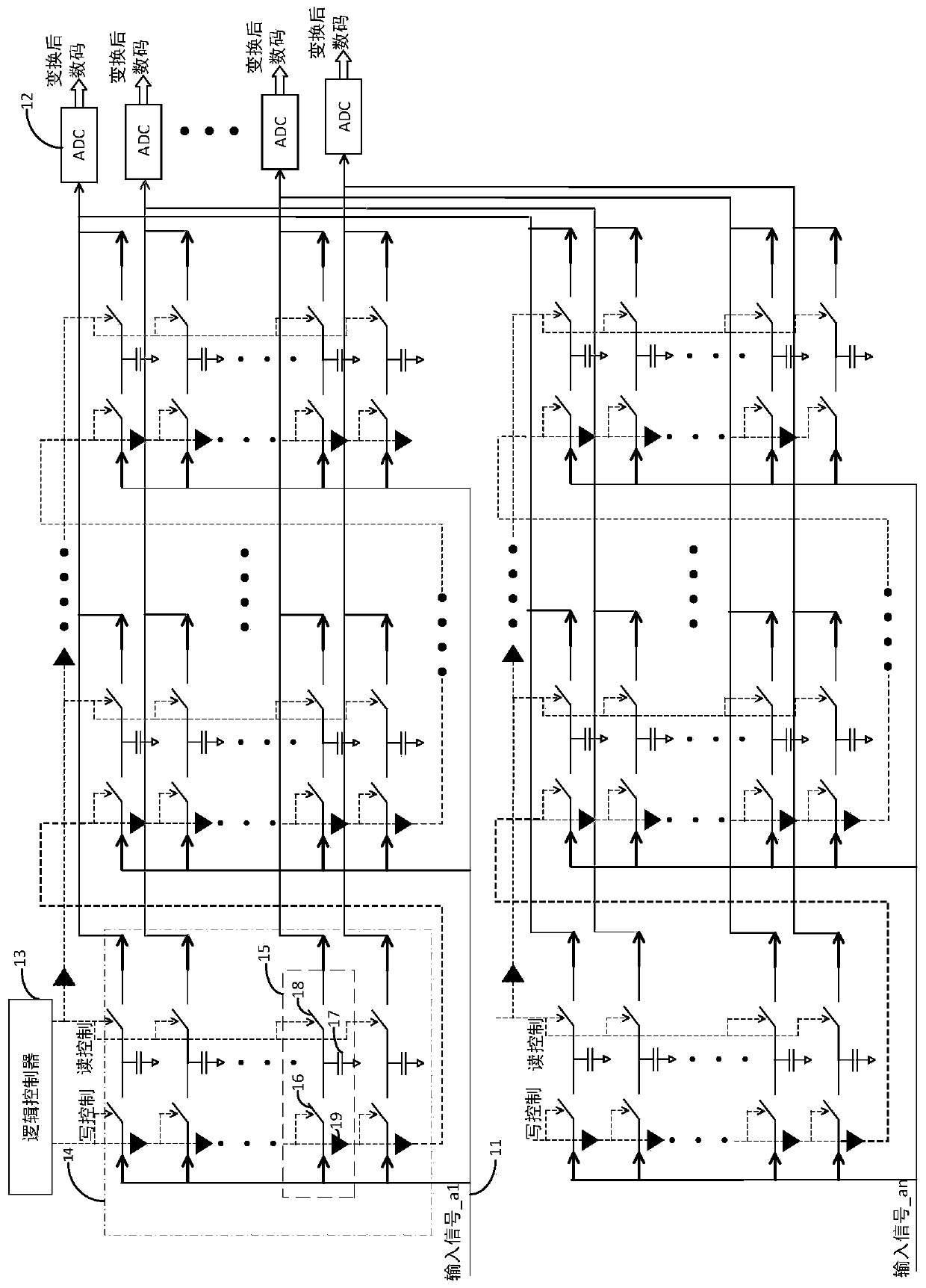
[0023] figure 1 A circuit for digitizing array radar signals provided by Embodiment 1 of the present invention is shown. For convenience of description, only parts related to the embodiment of the present invention are shown.
[0024] The circuit for digitalizing array radar signals in the embodiment of the present invention includes N sampling channels 11, M analog-to-digital converters (ADCs) 12 and logic controllers 13, except that each sampling channel 11 shares M ADCs 12, The circuit structure of each sampling channel 11 is the same. A sampling channel 11 includes L sampling unit groups 14, each sampling unit group 14 includes M sampling units 15, and each sampling unit 15 includes an input switch 16, a sampling and holding capacitor 17 and an output switch 18, each In each sampling unit 15, one end of the capacitor 17 is connected to the input switch 16 and the output switch 18, and the other end of the output switch 18 of the M sampling units 15 in each sampling unit g...
Embodiment 2
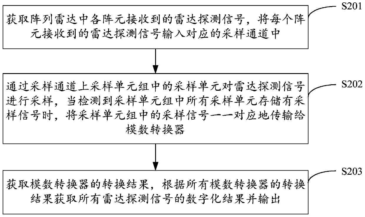
[0033] figure 2 It shows the implementation process of the method for digitizing array radar signals provided by Embodiment 2 of the present invention. For the convenience of description, only the parts related to the embodiment of the present invention are shown, and the details are as follows:
[0034] In step S201, the radar detection signal received by each array element in the array radar is acquired, and the radar detection signal received by each array element is input into a corresponding sampling channel.
[0035] In the embodiment of the present invention, radar detection signals received by each array element in the array radar are obtained, and these radar detection signals are respectively input into corresponding sampling channels, so as to sample these radar detection signals. Preferably, the number of sampling channels is the same as the number of elements of the array radar, so that the radar signals of the multi-element radar can be processed simultaneously,...
Embodiment 3
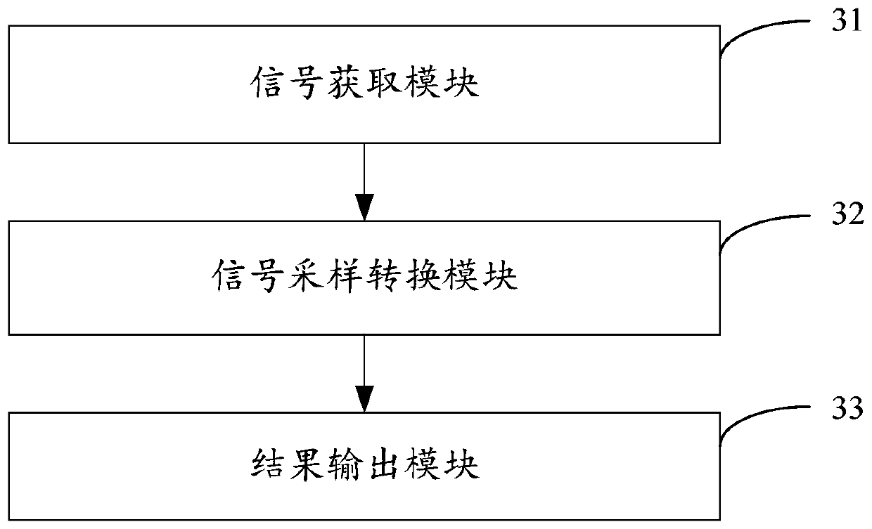
[0046] image 3 The structure of the device for digitizing array radar signals provided by Embodiment 3 of the present invention is shown. For the convenience of description, only the parts related to the embodiment of the present invention are shown, including:
[0047] The signal acquisition module 31 is configured to acquire radar detection signals received by each array element in the array radar, and input the radar detection signals received by each array element into a corresponding sampling channel.
[0048] In the embodiment of the present invention, radar detection signals received by each array element in the array radar are obtained, and these radar detection signals are respectively input into corresponding sampling channels, so as to sample these radar detection signals. Preferably, the number of sampling channels is the same as the number of elements of the array radar, so that the radar signals of the multi-element radar can be processed simultaneously, and the...
PUM
 Abstract
Description
Claims
Application Information
 - R&D
- Intellectual Property
- Life Sciences
- Materials
- Tech Scout
- Unparalleled Data Quality
- Higher Quality Content
- 60% Fewer Hallucinations
Browse by: Latest US Patents, China's latest patents, Technical Efficacy Thesaurus, Application Domain, Technology Topic, Popular Technical Reports.
© 2025 PatSnap. All rights reserved.Legal|Privacy policy|Modern Slavery Act Transparency Statement|Sitemap|About US| Contact US: help@patsnap.com


