Optical transceiver module housing and optical transceiver module

A technology of optical transceiver module and casing, which is applied in the field of optical communication, can solve problems such as exceeding the standard and affecting the electromagnetic shielding effect of the optical module casing, and achieve the effect of easy locking and unlocking

Pending Publication Date: 2018-04-13
LINKTEL TECH CO LTD
View PDF4 Cites 12 Cited by
  • Summary
  • Abstract
  • Description
  • Claims
  • Application Information

AI Technical Summary

Problems solved by technology

[0003] However, QSFP28 is currently facing two problems. One is: because the optical communication module often needs to be plugged and pulled out when in use, it is usually required that the module has an unlocking device so that the module can be removed from the installation cage of the equipment smoothly. The other one is: with the continuous improvement of the transmission rate of the optical module, the high-transmission optical transceiver module is particularly prone to excessive EMI (electromagnetic int

Method used


Image

  • Optical transceiver module housing and optical transceiver module
  • Optical transceiver module housing and optical transceiver module
  • Optical transceiver module housing and optical transceiver module

Examples


Example Embodiment

[0033] The technical solutions in the embodiments of the present invention will be clearly and completely described below in conjunction with the accompanying drawings in the embodiments of the present invention. Obviously, the described embodiments are only a part of the embodiments of the present invention, rather than all the embodiments. Based on the embodiments of the present invention, all other embodiments obtained by those of ordinary skill in the art without creative work shall fall within the protection scope of the present invention.
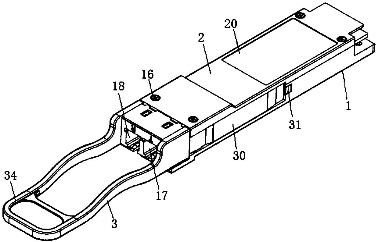
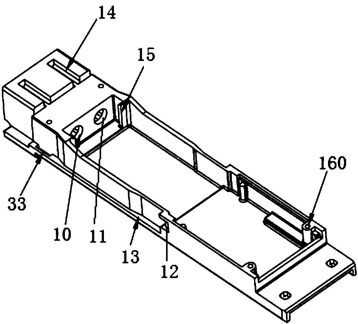
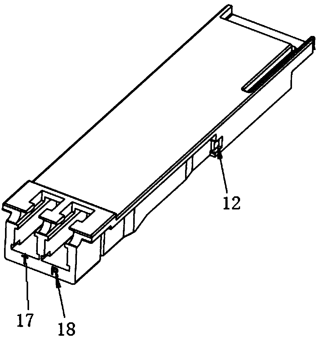
[0034] See Figure 1-Figure 9 , The embodiment of the present invention provides an optical transceiver module housing, which includes a housing 1 and a cover 2. The cover 2 is used to seal the housing 1 and eliminate the communication between the cavity of the housing 1 and the outside as much as possible, which can avoid Electromagnetic waves leak from the inside of the housing 1 to the outside. The cover 2 is detachably installed on ...


PUM


Abstract

The invention relates to the technical field of optical communication and provides an optical transceiver module housing comprising a housing, a cover body for sealing the housing, and a handle that can sleeve the housing. The cover body is detachably mounted on the housing. The housing has a cavity for installing a light emitting device and a light receiving device. A side of the housing is provided with a first through hole and a second through hole for the light emitting device and the light receiving device to be inserted respectively. The handle has two bar-shaped locking pieces. Lockingheads are disposed at the end portions of the two locking pieces. Both sides of the housing are provided with first grooves for the two locking heads to be engaged with respectively. An optical transceiver module is also provided which includes a light emitting device, a light receiving device, and the above optical transceiver module housing. The optical transceiver module housing and the opticaltransceiver module each leads to the outside via the two through holes such that the possibility that electromagnetic waves leave from other slits is greatly reduced. Locking and unlocking can be easily achieved by engaging or disengaging the locking heads on the locking pieces with a first recess.

Description

technical field [0001] The invention relates to the technical field of optical communication, in particular to an optical transceiver module shell and an optical transceiver module. Background technique [0002] The development trend of high integration and high speed of optical communication modules will inevitably make optical modules continue to develop in the direction of high speed, miniaturization, and high density. Therefore, QSFP28 pluggable 100G high-speed optical transceiver module came into being. QSFP28 optical module is a high-density, high-speed product solution designed for optical communication, data center and network market applications. The cost and power consumption of a data center is one of the important factors that its builders need to consider, which is also an important driving force for the development of the optical communication market. Looking back at the development history of 100G optical modules, the development and improvement of its packag...

Claims


Application Information

Patent Timeline
IPC IPC(8): G02B6/42H04B10/40
CPCH04B10/40G02B6/4261G02B6/4277
Inventor 彭峰张健杨现文吴天书李林科
Owner LINKTEL TECH CO LTD
Why Eureka
Try Eureka