Drainage consolidation method for soft foundation

A technology of drainage consolidation and soft soil foundation, which is applied in basic structure engineering, soil protection, construction, etc., can solve the problems of increased construction cost, complicated construction, and high construction cost, so as to speed up the construction progress, simplify the construction process, reduce the The effect of construction costs

Active Publication Date: 2018-04-17
WUHAN UNIV
View PDF10 Cites 10 Cited by
  • Summary
  • Abstract
  • Description
  • Claims
  • Application Information

AI Technical Summary

Problems solved by technology

The two types of methods are to first set up horizontal drainage bodies (sand cushion, blind ditch, water collection wells, etc.) and vertical drainage bodies (plastic drainage boards, sand wells, etc.), and then load (dynamic load, static load or static load or dynamic load). Alternate application of load) to accelerate the drainage and consolidation of soft soil, the discharged pore water is discharged to the sand cushion layer through plastic drainage boards or sand wells, and then discharged to designated locations or collected in water collection wells through blind ditch, and then discharged with water pumps, such as in China Patent CN 105002883 A discloses an indirect graded relay drainage consolidation method for weak foundations, which is mainly aimed at the weak foundations formed by the reclamation of the sea in the lower saturated clay layer and the upper dredged fill soil layer. A horizontal transfer layer is formed within the depth range above the top surface of the lower saturated cohesive soil layer, a static drainage channel is set in the lower saturated cohesive soil layer, a dynamic drainage channel is set in the upper dredging fill soil layer, and the groundwater in the lower soil layer is discharged to the horizontal transfer layer After ...

Method used


Image

  • Drainage consolidation method for soft foundation
  • Drainage consolidation method for soft foundation

Examples


Embodiment Construction

[0024] The specific implementation of the drainage consolidation method for soft soil foundation involved in the present invention will be described in detail below in conjunction with the accompanying drawings.

[0025]

[0026] The soft ground drainage consolidation method provided by the present embodiment comprises the following steps:

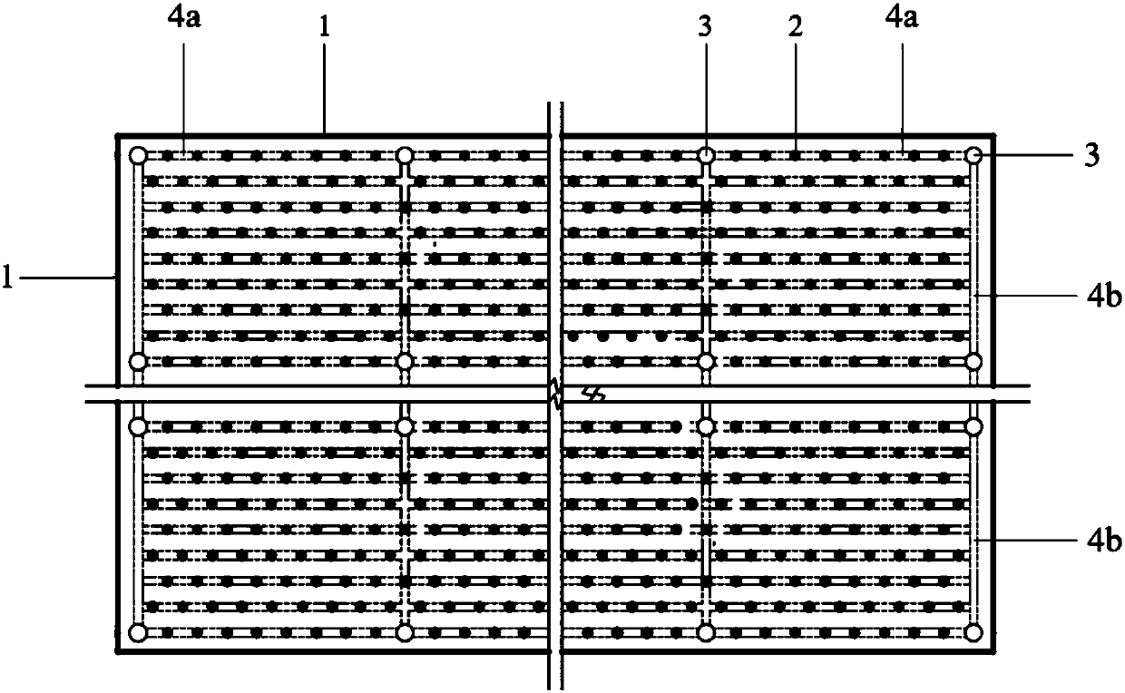
[0027] Step 1. In the drainage consolidation area, divide the area into several sub-areas with a length of 100m and a width of 50m.

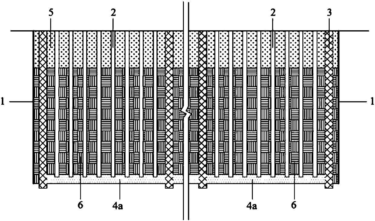
[0028] Step 2. If figure 1 and 2 As shown, at the boundary of the sub-area, the vertical geomembrane anti-seepage layer 1 extending along the depth direction perpendicular to the ground is constructed. First, the lower end of the geomembrane is wound on the steel wire. First, the soil body is torn apart, and then the geomembrane is driven into the soil body to form a vertical geomembrane anti-seepage layer 1 .

[0029] Step 3. In the soft soil at the bottom of the soft soil foundation in the sub-region,...


PUM


Abstract

The invention provides a drainage consolidation method for a soft foundation. The drainage consolidation method for the soft foundation is characterized by comprising the following steps that firstly,a drainage consolidation area is divided into a plurality of sub-areas; secondly, on the boundaries of the sub-areas, vertical geomembrane impermeable layers perpendicular to the ground are constructed; thirdly, a plurality of first sand layers and second sand layers are constructed in bottom soft soil, and in this way, permeable channels intersecting longitudinally and transversely on a horizontal plane are formed; fourthly, a plurality of sand wells or drain boards are at least constructed on the first sand layers and the second sand layers located on the inner layer, and a vertical water draining structure with the bottom embedded in the permeable channels is formed; and fifthly, a plurality of water collecting wells are constructed at least on the first sand layers and the second sandlayers located on the outer layer, the adjacent water collecting wells in the length direction are located on the two adjacent second sand layers separately, the multiple first sand layers are arranged between the adjacent water collecting wells in the width direction at intervals, the bottoms of the water collecting wells are embedded into the permeable channels, then water in the water collecting wells is drained out, water draining of the sub-areas is completed, and solidification of soil is accelerated.

Description

technical field [0001] The invention belongs to the technical field of soft soil foundation treatment in geotechnical engineering, and in particular relates to a method for drainage and consolidation of soft soil foundations. technical background [0002] In order to alleviate the constraints of land resources on the economic development of coastal areas, many coastal areas in my country have formed land areas through land reclamation. Firstly, construct the enclosing and twisting project to enclose the shallow sea to form a fixed dredging reclamation area, then mix the bottom mud of the dredged channel or shallow sea silt with seawater in a certain proportion to form mud, and transport it to the dredging reclamation area with a blowpipe. Water and consolidation form a land area, so the formed soft soil foundation has engineering characteristics such as high water content, high compressibility, high void ratio, high sensitivity, poor structure, and low degree of consolidatio...

Claims


Application Information

Patent Timeline
IPC IPC(8): E02D3/10
Inventor 陈明叶志伟卢文波严鹏王高辉
Owner WUHAN UNIV
Why Eureka
Try Eureka