Check patentability & draft patents in minutes with Patsnap Eureka AI!

OLED pixel driving circuit, driving method and OLED display device

A pixel driving circuit and driving method technology, applied to static indicators, instruments, etc., can solve the problems affecting the luminance and unevenness of the light-emitting device OLED, and the bad influence of the display effect of the OLED display panel, etc.

Active Publication Date: 2018-04-17
BOE TECH GRP CO LTD +1
View PDF8 Cites 11 Cited by
  • Summary
  • Abstract
  • Description
  • Claims
  • Application Information

AI Technical Summary

Problems solved by technology

[0006] According to the above formula, the driving current for driving the light-emitting device OLED to emit light is related to the threshold voltage Vth of the driving transistor, and in practical applications, the threshold voltage Vth of the driving transistor will drift during the light-emitting stage, which will affect the light-emitting brightness of the light-emitting device OLED. It makes it uneven during the light emitting process, which will have a negative impact on the display effect of the OLED display panel

Method used


Image

  • OLED pixel driving circuit, driving method and OLED display device
  • OLED pixel driving circuit, driving method and OLED display device
  • OLED pixel driving circuit, driving method and OLED display device

Examples


Embodiment Construction

[0044] In order to make the above objects, features and advantages of the present invention more comprehensible, the present invention will be further described in detail below in conjunction with the accompanying drawings and specific embodiments.

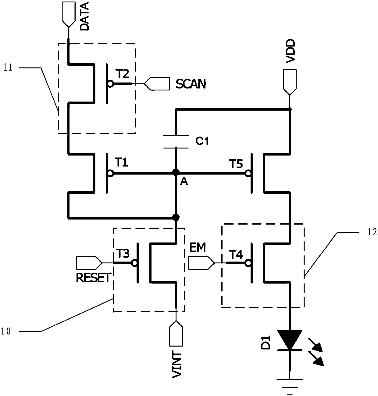
[0045] In an embodiment provided by this application, refer to figure 1, shows a schematic structural diagram of an OLED pixel drive circuit, which is used to drive the light emitting device in the OLED pixel to emit light, and may include a first transistor T1, a drive transistor T5, a storage capacitor C1, a reset module 10, a charging The control module 11 and the lighting control module 12 . The first pole of the first transistor T1 is connected to the charging control module 11, the control pole and the second pole of the first transistor T1 are both connected to the first end of the storage capacitor C1; the charging control module 11 is also connected to the data signal input terminal DATA and the scanning The signal input...


PUM


Abstract

The invention provides an OLED pixel driving circuit for driving a light emitting device in an OLED pixel to emit light, a driving method and an OLED display device. The OLED pixel driving circuit comprises a first transistor, a driving transistor, a storage capacitor, a reset module, a charging control module and a light emitting control module. Through the charging control module, the first-endvoltage of the storage capacitor rises to Vdata-|Vth1|. When the driving transistor and the light emitting device are conducted, the generated driving current is related to the difference value between threshold voltage of the first transistor and threshold voltage of the driving transistor, the difference value between the threshold voltage of the first transistor and the threshold voltage of thedriving transistor is smaller than a preset value, and thus, the light emitting brightness changes of the light emitting device can be controlled within a preset range, a picture uneven phenomenon generated by drift of the threshold voltage of the driving transistor is thus eliminated.

Description

technical field [0001] The invention relates to the technical field of display panels, in particular to an OLED pixel drive circuit and a drive method, and an OLED display device. Background technique [0002] The active matrix organic light emitting diode (Active Matrix Organic Light Emitting Diode, hereinafter referred to as AMOLED) display panel uses OLED to emit light of different brightness, so that the pixels corresponding to OLED display have corresponding brightness; compared with the traditional thin film transistor liquid crystal display panel (Thin Film Transistor Liquid Crystal Display, hereinafter referred to as TFT LCD), AMOLED display panel has faster response speed, higher contrast ratio and wider viewing angle, which is an important development direction of display panel. [0003] The current that drives OLED to emit light can be expressed by the following formula: [0004] [0005] Wherein, Vgs is the voltage difference between the gate and the source o...

Claims


Application Information

Patent Timeline
IPC IPC(8): G09G3/3208
CPCG09G3/3208
Inventor 韩文出杨富成蒋璐霞聂军
Owner BOE TECH GRP CO LTD
Features
  • R&D
  • Intellectual Property
  • Life Sciences
  • Materials
  • Tech Scout
  • Unparalleled Data Quality
  • Higher Quality Content
  • 60% Fewer Hallucinations
Learn More