Automatic gain control receiver

A technology of automatic gain control and receiver, applied in the field of communication, can solve the problems of small dynamic range, low control precision and slow control speed of automatic gain control.

Active Publication Date: 2018-04-17
ARMY ENG UNIV OF PLA
View PDF5 Cites 5 Cited by
  • Summary
  • Abstract
  • Description
  • Claims
  • Application Information

AI Technical Summary

Problems solved by technology

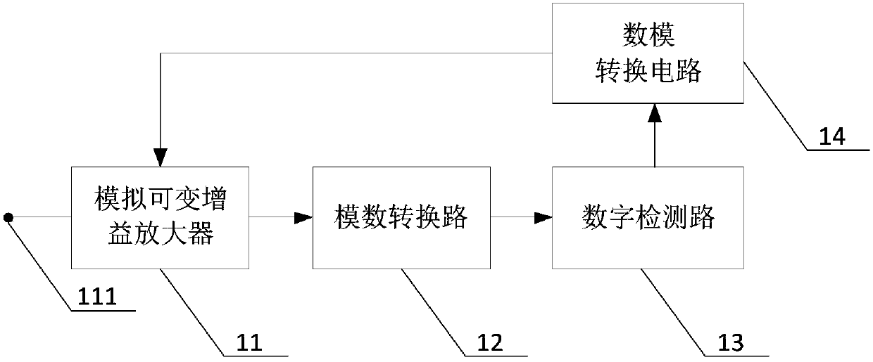
[0003] The technical problem to be solved by the present invention is to provide an automatic gain control receiver, which solves the problems of small dynamic range, low control precision, slow control speed and susceptibility to interference of the receiver in the prior art

Method used


Image

  • Automatic gain control receiver
  • Automatic gain control receiver
  • Automatic gain control receiver

Examples


Embodiment Construction

[0018] Various embodiments of the present invention will be described in detail below in conjunction with the accompanying drawings.

[0019] In order to facilitate the understanding of the present invention, the present invention will be described in more detail below in conjunction with the accompanying drawings and specific embodiments. Preferred embodiments of the invention are shown in the drawings, but the invention can be realized in many different forms and is not limited to the embodiments described in this specification. On the contrary, these embodiments are provided to make the understanding of the disclosure of the present invention more thorough and comprehensive.

[0020] It should be noted that, unless otherwise defined, all technical and scientific terms used in this specification have the same meaning as commonly understood by those skilled in the technical field of the present invention. Terms used in the description of the present invention are only for th...


PUM


Abstract

The invention relates to an automatic gain control receiver. The receiver consists of an analog variable gain amplifier, an analog to digital conversion circuit, a digital detection circuit and a digital to analog conversion circuit, which are electrically connected with each other in sequence, an output end of the digital to analog conversion circuit is electrically connected with a gain controlend of the analog variable gain amplifier, so that an output signal of the digital detection circuit performs automatic adjustment and control on the gain of the analog variable gain amplifier. By adoption of the automatic gain control receiver, the automatic gain control can be performed on the input analog radio frequency signal, so that the analog radio frequency signal can have signal output of stable power within a greater dynamic range, and the signal power can be quickly and accurately detected through the digital detection circuit so as to feed back and control the gain of the analog variable gain amplifier, and the automatic gain control receiver has the technical advantages of wide dynamic range of controlling the radio frequency signal, high control precision, fast control speedand little interference from the outside.

Description

technical field [0001] The invention relates to the technical field of communication, in particular to an automatic gain control receiver. Background technique [0002] With the development of electronic technology, radio communication receivers occupy an increasingly important position in the entire electronic field. Due to the influence of transmitting power, radio wave propagation fading, receiving signal conditions and other interference factors, the dynamic range of the signal at the input of the receiver will be large, and the output power of the receiver changes with the size of the external input signal. Therefore, there will be very different signal powers at the output of the receiver. If the signal amplification gain is too large, the receiver will be in a nonlinear state, which may generate harmonics; if the amplification gain is insufficient, the received signal may be too small, which is not conducive to subsequent demodulation. Therefore, it is necessary to ...

Claims


Application Information

Patent Timeline
Patent Type & Authority Applications(China)
IPC IPC(8): H04B1/16
CPCH04B1/16
Inventor 朱银霞张剑程剑李广侠朱宏鹏朱文明石盛超唐瑾宇朱鑫昱徐星辰
Owner ARMY ENG UNIV OF PLA
Why Eureka
Try Eureka