Voltage regulating equipment based on single-chip microcomputer
A single-chip microcomputer and equipment technology, which is applied to the parts of the connection device, the device for joining/disconnecting the connection parts, and electrical components, etc., can solve the problem of wire falling off, easy bifurcation, and reducing the contact surface between the wire and the fixed block and other problems to achieve the effect of increasing friction and avoiding falling off
- Summary
- Abstract
- Description
- Claims
- Application Information
AI Technical Summary
Problems solved by technology
Method used
Image
Examples
Embodiment 1
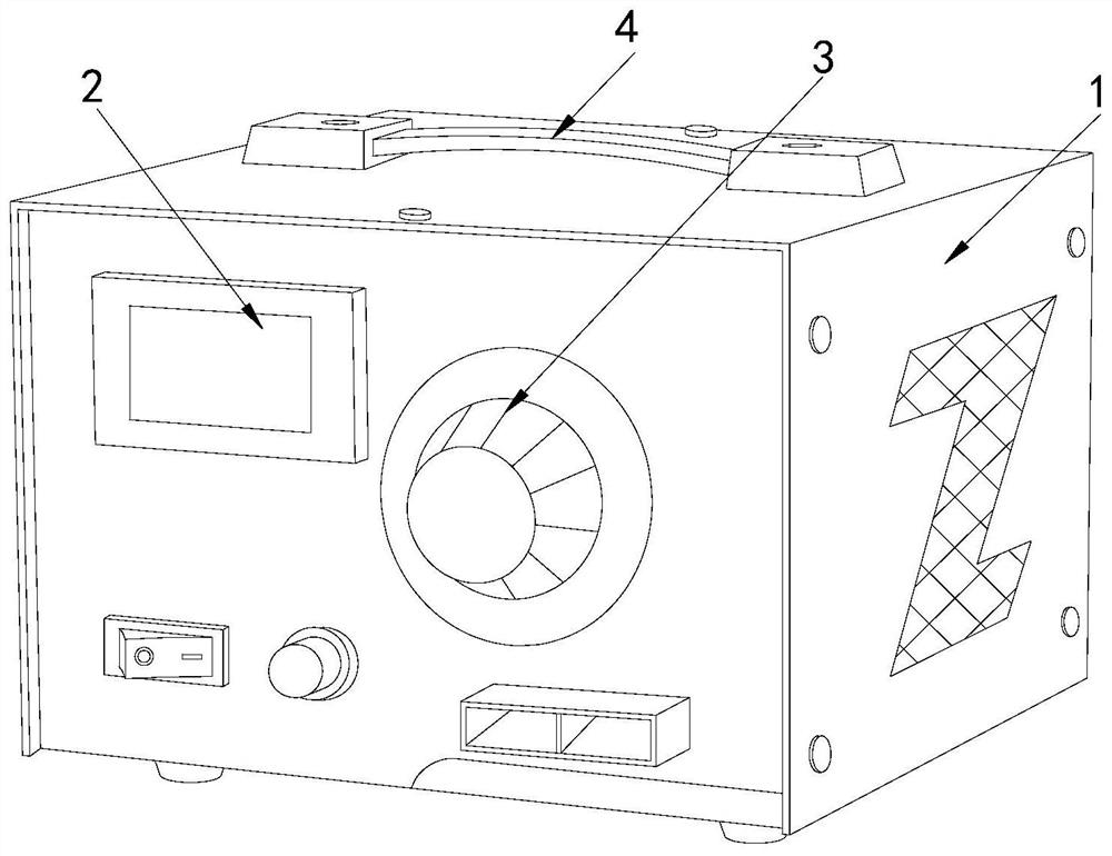
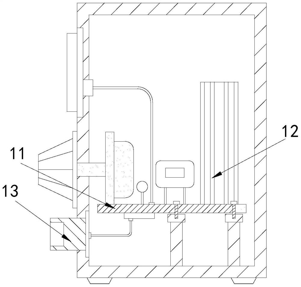
[0024] Example 1: Please refer to Figure 1-Figure 5 , the specific embodiments of the present invention are as follows:
[0025] Its structure includes a main body 1, a display screen 2, an adjustment button 3, and a handle 4. The front top of the main body 1 is provided with a display screen 2, the adjustment button 3 is arranged at the right end of the display screen 2, and the handle 4 is engaged with the In the middle of the top of the main body 1, the main body 1 includes a circuit board 11, a heat sink 12, and a power connector 13. The circuit board 11 is horizontally installed in the middle of the bottom of the main body 1, and the heat sink 12 is arranged on the bottom of the circuit board 11. On the top side, the power connector 13 is arranged at the bottom of the front end of the main body 1 .
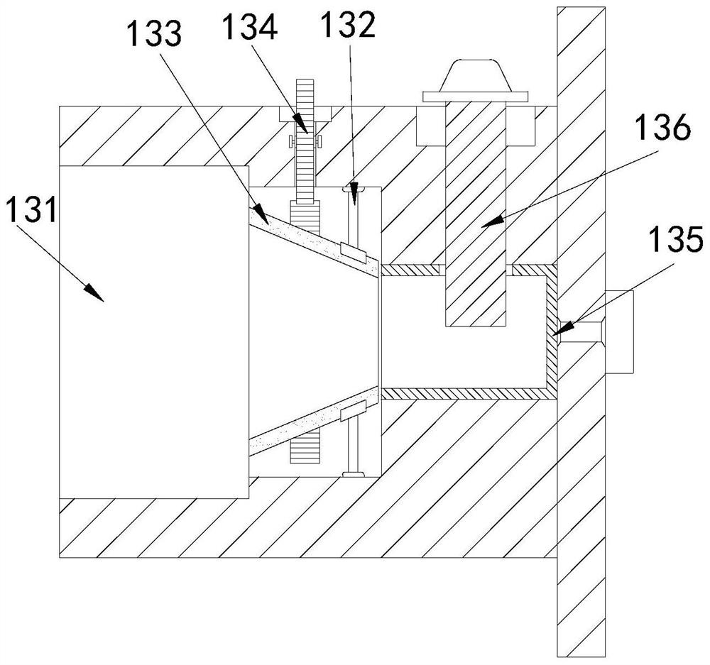
[0026] The power connector 13 includes a recessed groove 131, an engaging frame 132, a lead frame 133, an adjustment tooth block 134, a conductive frame 135, and a pressing...
Embodiment 2
[0030] Example 2: Please refer to Figure 6-Figure 7 , the specific embodiments of the present invention are as follows:
[0031] The pressing device 136 includes an engaging block b1, a rotating button b2, a screw rod b3, a lifting block b4, a spiral groove b5, and a pressing block b6. The inner top of the engaging block b1 is engaged with the rotating button b2, so that The screw rod b3 is embedded in the middle of the bottom of the rotary button b2, the lifting block b4 is engaged with the inner bottom end of the engaging block b1, the spiral groove b5 is located at the inner side end of the lifting block b4, and the pressing down The block b6 is embedded in the bottom end of the lifting block b4, and the screw rod b3 is screwed with the spiral groove b5, which is beneficial to drive the screw rod b3 and the screw groove b5 by turning the rotation button b2, so that the lifting block b4 can move up and down. Move, the wire is fixed in the conductive frame 135 by the lower ...
PUM
 Abstract
Description
Claims
Application Information
 - R&D
- Intellectual Property
- Life Sciences
- Materials
- Tech Scout
- Unparalleled Data Quality
- Higher Quality Content
- 60% Fewer Hallucinations
Browse by: Latest US Patents, China's latest patents, Technical Efficacy Thesaurus, Application Domain, Technology Topic, Popular Technical Reports.
© 2025 PatSnap. All rights reserved.Legal|Privacy policy|Modern Slavery Act Transparency Statement|Sitemap|About US| Contact US: help@patsnap.com


