
Centrifugal fish feeder

A centrifugal and logic controller technology, applied in the field of fish feeders, can solve the problems of increasing motor power, increasing energy consumption, and single angle, and achieves the effects of increasing centrifugal force, easy assembly, and simple structure

Inactive Publication Date: 2018-04-20
陈雪美
View PDF0 Cites 1 Cited by
  • Summary
  • Abstract
  • Description
  • Claims
  • Application Information

AI Technical Summary

Problems solved by technology

[0002] The fish feeder is mainly used in the feeding of fish in fish ponds. It replaces the traditional manual feeding through its automatic function, which saves a lot of manpower and material resources to a certain extent. The output is low and the income is low, which cannot meet the needs of people for large-scale breeding. Later, mechanical feeding machines appeared, which increased the breeding area and production, and also improved the economic benefits of farmers. Due to the limitations of the fish, a large number of fish concentrate in the process of eating, resulting in hypoxia, especially the fish in the middle area are prone to indigestion and other diseases due to overeating, and the fish in the periphery eat less or cannot eat, resulting in slow growth , malnutrition and other problems, thereby reducing the yield of fish farming
[0003] Most of the current feed feeding equipment uses the method of throwing or spraying the feed to the surroundings. For the throwing type machinery, the angle is single, and the throwing distance is difficult to change. The angle is not enough, but the distance of feeding is limited by the jet airflow, the length of the conveying pipeline, etc., the range is still not enough, and it is only suitable for small and medium-sized aquaculture ponds
[0004] For some centrifugal fish feeders, the throwing distance is not enough. Increasing the power of the motor increases energy consumption and noise, which will scare away many fish. In addition, the single function of the fish feeder has become a problem to be solved at present.

Method used


Image

  • Centrifugal fish feeder
  • Centrifugal fish feeder
  • Centrifugal fish feeder

Examples


Embodiment Construction

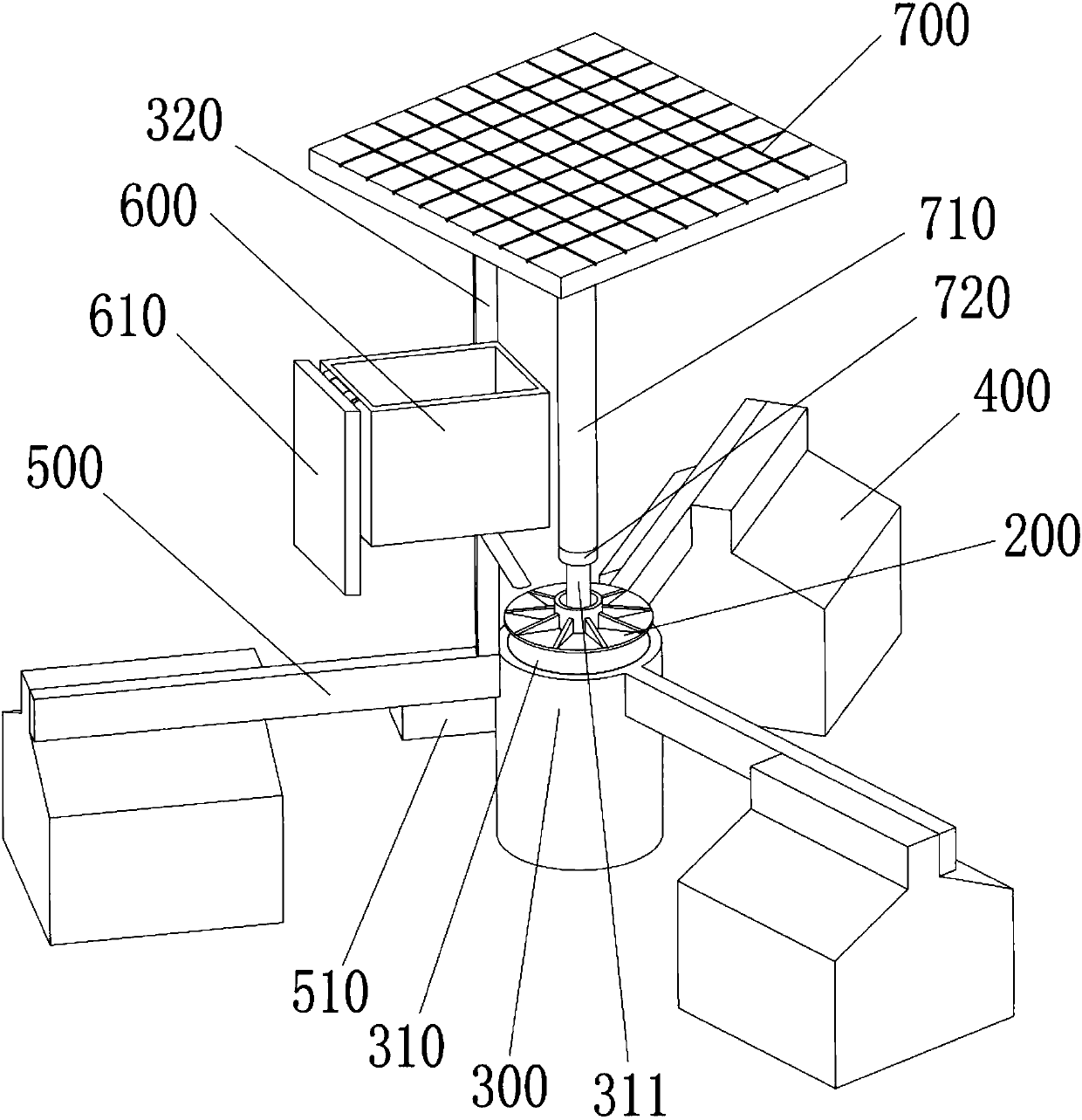
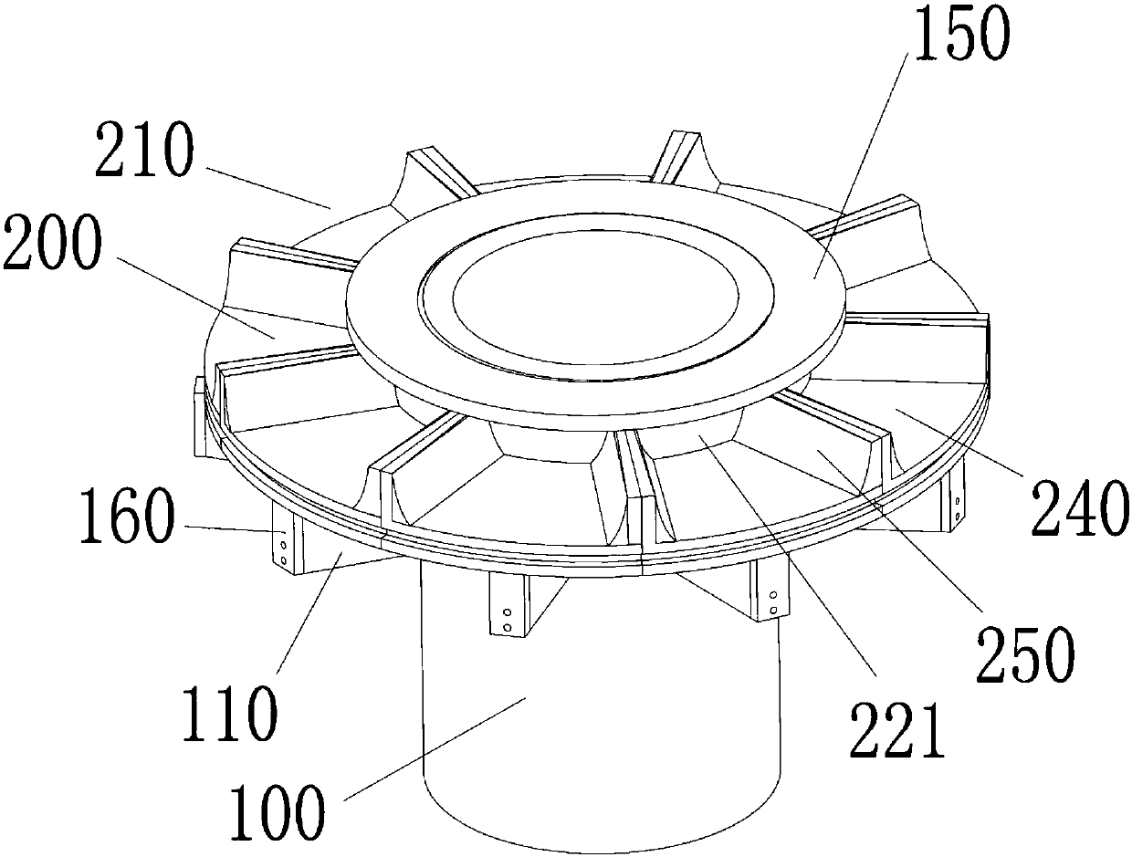
[0033] Such as figure 1 - As shown in the figure, a centrifugal fish feeder is characterized in that it includes a connection base 300, a cavity 310 for accommodating a motor and a power supply is provided in the connection base 300, and several buoys 400 are included to float the connection base 300 on the water surface , the connection seat 300 is fixedly connected with the buoy 400 through the strut 500, including the tray assembly for feeding, the tray assembly is fixedly connected with the output shaft 311 of the motor, when the motor is working, the tray assembly rotates to realize feeding, the strut 500 and the buoy 400 It can be fixed by screws. The tray assembly includes a base body 100 and a tray 200 , which are collectively referred to as a tray assembly here.

[0034] The tray assembly includes a seat body, the seat body 100 is a hollow tubular structure, the side wall of the seat body 100 is provided with several symmetrical guide rails 110, and the guide rails 11...


PUM


Abstract

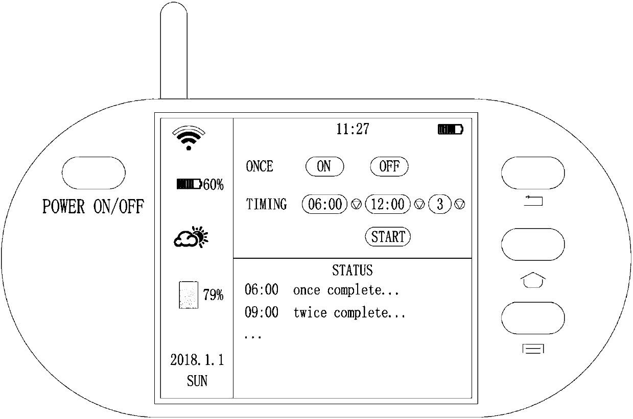
The invention relates to a fish feeder and especially relates to a centrifugal fish feeder used in culture ponds. The fish feeder comprises a connecting seat; the connecting seat is provided with an accommodating motor and a power supply chamber; the fish feeder comprises multiple floating drums by which the connecting seat floats on the water surface; a pallet assembly rotates to realize feeding.According to the invention, a feeding pallet is designed to reciprocate by means of the centrifugation and centripetal motion principles; the centrifugation motion is accelerated by the returning ofa return spring and cooperation of balls; a stop board with a bevel on the pallet increases the angle of food leaving the tray. A series of designs increase the range of food projections. In the caseof keeping the power of the motor unchanged, the centrifugal force is increased, the utility is strong, the structure is simple, the processing is convenient, and the assembly is easy; the entire equipment is propped up by the floating drums, so that the equipment is stable and floats on the water; and the solar power supply is added, and the offshore wiring is eliminated; the wireless module is set up to facilitate remote control of feeding; timers were added to enable all-day leave unattended operations.

Description

technical field [0001] The invention relates to a fish feeder, in particular to a centrifugal fish feeder for aquaculture ponds. Background technique [0002] The fish feeder is mainly used in the feeding of fish in fish ponds. It replaces the traditional manual feeding through its automatic function, which saves a lot of manpower and material resources to a certain extent. The output is low and the income is low, which cannot meet the needs of people for large-scale breeding. Later, mechanical feeding machines appeared, which increased the breeding area and production, and also improved the economic benefits of farmers. Due to the limitations of the fish, a large number of fish concentrate in the process of eating, resulting in hypoxia, especially the fish in the middle area are prone to indigestion and other diseases due to overeating, and the fish in the periphery eat less or cannot eat, resulting in slow growth , Malnutrition and other problems, thereby reducing the yie...

Claims


Application Information

Patent Timeline
IPC IPC(8): A01K61/80
CPCA01K61/80Y02A40/81Y02P60/60
Inventor 叶盛周施施陈雪美
Owner 陈雪美
Learn More