
Dust removal device for textile production

A technology of dust removal device and textile room, which is applied in the direction of using liquid separation agent, dispersed particle separation, chemical instruments and methods, etc., can solve the problems of human health injury, adsorption and blockage of dust removal device, affecting dust removal efficiency, etc., to improve efficiency and Comprehensiveness, increase the falling collection speed, and ensure the effect of dust removal efficiency

Inactive Publication Date: 2018-04-20
瑞安市异想天开科技有限公司
View PDF5 Cites 5 Cited by
  • Summary
  • Abstract
  • Description
  • Claims
  • Application Information

AI Technical Summary

Problems solved by technology

[0003] The purpose of the present invention is to provide a dust removal device for textile production in order to solve the above problems, which solves the problem that when the existing textile equipment performs textile work, a large amount of textile fiber dust will be generated, and the staff will enter through breathing when they inhale. Into the body, in the long run, it can cause respiratory infection or even lung disease, causing great harm to human health, and textile fiber dust will carry static electricity during the weaving process, and the adsorption force of static electricity will cause textile fiber dust to adsorb and block the dust removal device , the problem that affects the dust removal efficiency

Method used


Image

  • Dust removal device for textile production
  • Dust removal device for textile production
  • Dust removal device for textile production

Examples


Embodiment Construction

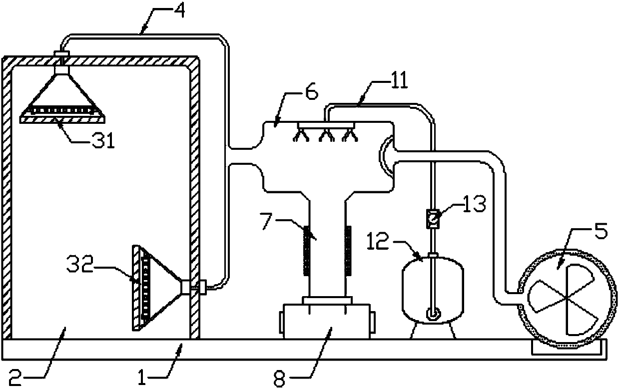
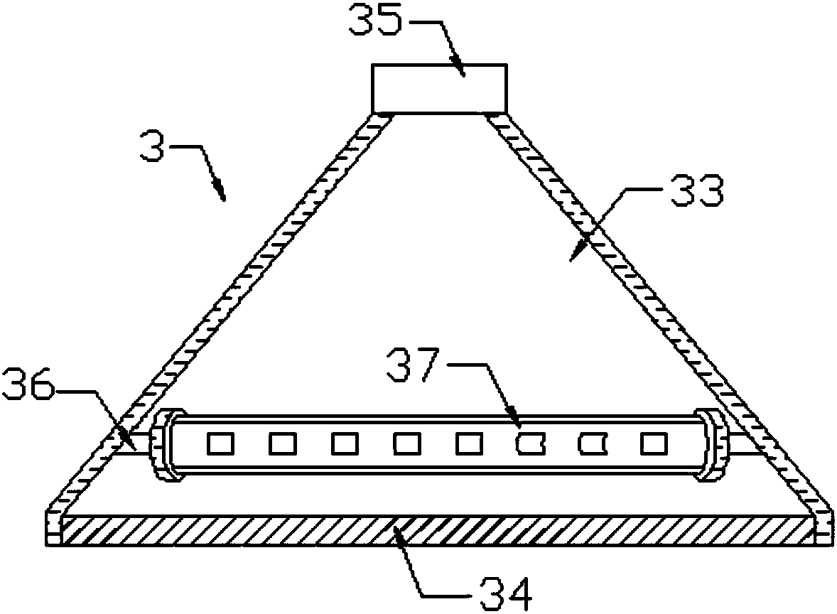
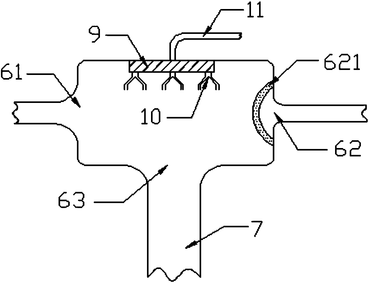
[0021] Such as Figure 1-Figure 4 As shown, this specific embodiment adopts the following technical solutions: a dust removal device for textile production, including a base 1, a textile chamber 2 is arranged on one end of the top of the base 1, and a dust removal device is installed inside the textile chamber 2. Suction hood 3, the dust removal hood 3 is connected to the dust removal fan 5 through the dust delivery pipe 4, the dust removal fan 5 is installed on the base 1 far away from the end of the weaving room 2, between the weaving room 2 and the dust removal fan 5 A dust-falling pipe 6 is fixedly installed on the dust-feeding pipe 4 between them, and the dust-falling pipe 6 includes an air inlet 61, an air outlet 62 and a dust-falling port 63, and the air inlet 61 and the air outlet 62 are respectively arranged on two opposite sides of the dust-falling pipe 6. On the end, the dust falling port 63 is arranged at the bottom of the dust falling pipe 6, the dust falling pipe...


PUM


Abstract

The invention discloses a dust removal device for textile production. A textile chamber is arranged on one end of the top of the base; dust removal and air suction covers are arranged inside the textile chamber; the dust removal and air suction covers are connected with a dust removal fan through a dust conveying pipe; the dust removal fan is arranged on the base arranged at one end far away fromthe textile chamber; a dust reduction pipe is fixedly arranged on the dust conveying pipe arranged between the textile chamber and the dust removal fan. The dust removal device has the advantages thatthe structure is reasonable and simple; the dust removal efficiency is high; the use is convenient; the textile chamber is enabled to be clean; the textile quality influence due to dust adsorption onthe textile product in the spinning process is avoided; electrostatic elimination bars are arranged inside the first dust removal and air suction cover and the second dust removal and air suction cover, so that textile fiber dust passing though the first dust removal and air suction cover and the second dust removal and air suction cover can be subjected to electrostatic elimination; the dust conveying pipe blockage caused by dust adsorption on the dust conveying pipe due to the electrostatic adsorption force carried in the textile fiber dust is avoided; the dust removal efficiency of the dust removal device is further ensured.

Description

Technical field: [0001] The invention relates to the technical field of textile dust removal equipment, in particular to a dust removal device used in textile production. Background technique: [0002] As the upstream industry of the textile industry, the trend of textile machinery depends entirely on the prosperity of the textile industry. The textile industry is a traditional advantageous industry in my country. Textile products are also important foreign trade products in my country. As the main raw materials for daily-use products such as clothing, the textile industry The speed of development will also determine the supply and demand relationship and price changes of clothing, textile machinery and other industries. The rapid development of the textile industry is of great significance to the smooth operation of my country's economy and the maintenance of price stability. It occupies an important position in my country's economy. Textile equipment When doing textile work,...

Claims


Application Information

Patent Timeline
Patent Type & Authority Applications(China)
IPC IPC(8): B01D47/06
CPCB01D47/06
Inventor 朱天天
Owner 瑞安市异想天开科技有限公司
Learn More