Pipe blind hole cleaning device

A technology for cleaning devices and blind holes, applied in heating devices, cleaning hollow objects, cleaning methods and utensils, etc., can solve the problems of accelerated impurity adsorption speed, incompleteness, and short cleaning effect, and achieves thorough cleaning and long use time. Effect

Inactive Publication Date: 2018-04-20
重庆纵翼机械制造有限公司
View PDF9 Cites 2 Cited by
  • Summary
  • Abstract
  • Description
  • Claims
  • Application Information

AI Technical Summary

Problems solved by technology

[0005] The method of cleaning the blind hole in the above-mentioned patent documents is to remove the sludge by turning the straight handle twist or using the through hole on the straight handle to apply force, but because the drill bit or the through hole extending into the blind hole has a small contact range with the sl

Method used


Image

  • Pipe blind hole cleaning device
  • Pipe blind hole cleaning device

Examples


Embodiment 1

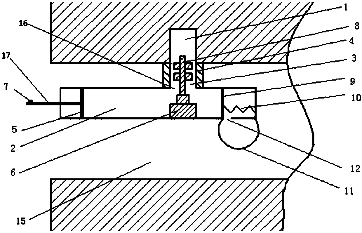
[0020] like figure 1 As stated, the blind hole cleaning device includes a housing 2, a cylinder body 3, a heating wire 4, a first piston 5, an automatic reciprocating cylinder 6, an automatic reciprocating cylinder switch device 7, a cleaning brush 8, a second piston 9, a spring 10 and Pocket 11. The casing 2 is cylindrical, and the casing 2 is provided with a first opening 16 and a second opening 12 . The barrel 3 is welded to communicate with the casing 2 at the first opening 16 . The heating wire 4 is detachably connected to the outer wall of the cylinder 3 by screws. The first piston 5 is slidingly fitted in the housing 2 , and the first piston 5 is coaxially welded with a handle 17 protruding from the housing 2 . The automatic reciprocating cylinder 6 is welded in the housing 2, and its output shaft is opposite to the opening of the cylinder body 3. Described cleaning brush 8 is connected on the output shaft of automatic reciprocating air cylinder 6 by screw thread. ...

Embodiment 2

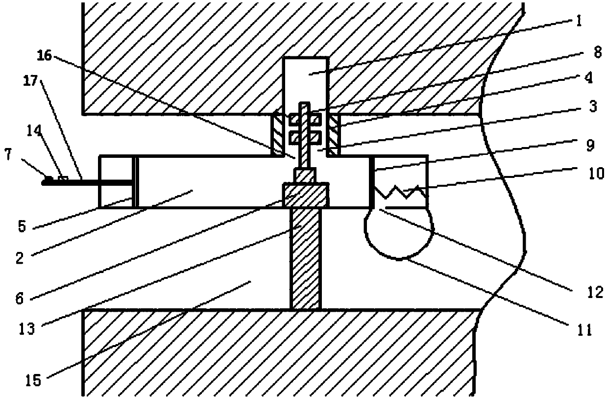
[0023] like figure 2 The structure schematic diagram of Embodiment 2 of the blind hole cleaning device, the difference between the blind hole cleaning device and the specific embodiment 1 is that this embodiment includes a support part 13 and a heating wire switch 14 . The support part 13 is installed on the outer wall of the shell 2 of the blind hole cleaning device, so that the blind hole cleaning device and the pipeline 15 are offset. The role of the support part 13 makes the cylinder body 3 and the wall of the blind hole 1 resist. When the first piston 5 is pushed, the pressure in the housing 2 increases. Since there is no gap between the cylinder body 3 and the blind hole 1, the solution No spillage for better cleaning environment. The heating wire switch 14 is installed on the handle 17, and is electrically connected with the heating wire 4. After the solution is drained, the heating wire switch 14 is pressed to make the heating wire 4 work, so that the heating wire 4 ...


PUM


Abstract

The invention relates to the technical field of cleaning devices, and in particular, discloses a blind hole cleaning device. The blind hole cleaning device comprises a shell, a cylinder, a heating device, a first piston, an automatic reciprocating cylinder, an automatic reciprocating cylinder switching device, a cleaning brush, a second piston, a spring and a pocket. The shell is provided with a first opening and a second opening; the cylinder communicates with the upper side of the shell; a heating device is arranged on the outer wall of the cylinder; the first piston is slidingly matched inthe shell, and is connected with a handle extending outside the shell; the automatic reciprocating cylinder is arranged in the shell, and an output shaft thereof is opposite to the first opening; thecleaning brush is arranged on the output shaft; the automatic reciprocating cylinder switching device is arranged on the handle; one end of the spring is connected with the shell, and the other end isconnected with the second piston; the second opening is formed in the connecting place of the spring, in a natural state, with the second piston; and the pocket is provided. The blind hole cleaning device can efficiently clean blind holes and lengthen the cleaning effect, and can be widely used for cleaning the blind holes in pipe inner walls.

Description

technical field [0001] The invention relates to a cleaning device, in particular to a blind hole cleaning device. Background technique [0002] At present, there are few researches on the cleaning process and special equipment of blind holes. The traditional way to clean blind holes is: spray cleaning. [0003] This cleaning method is that the pressure cleaning fluid is sprayed onto the blind hole through different nozzles, and the cleaning effect is achieved through the impact force. The disadvantage of this spray cleaning method is that stubborn impurities such as oil stains in the blind holes cannot be cleaned only by water pressure impact, and the work efficiency is low. [0004] In order to solve the above problems, Chinese patent CN104070043A discloses a blind hole cleaning tool, including a straight shank twist drill and a handle, the straight shank twist drill is set in the hole in the middle of the handle and fastened to form a T-shaped structure. There are two ax...

Claims


Application Information

Patent Timeline
IPC IPC(8): B08B9/043B08B13/00F26B23/06
CPCB08B9/0436B08B13/00F26B23/06
Inventor 蒋儒章
Owner 重庆纵翼机械制造有限公司
Why Eureka
Try Eureka