Low-cost container top plate hydraulic forming system

A hydraulic forming and container technology, which is applied in the field of hydraulic presses, can solve the problems of high procurement costs, achieve good synchronization, improve processing efficiency, and move smoothly

Active Publication Date: 2018-04-20
安徽金大进重工机床有限公司
View PDF11 Cites 2 Cited by
  • Summary
  • Abstract
  • Description
  • Claims
  • Application Information

AI Technical Summary

Problems solved by technology

[0006] The purpose of the present invention is to overcome the problem of high procurement cost of existing container roof blind wave forming equipment, and provide a low-cost container roof hydraulic forming system. The present invention is a special machine designed for the container roof structure. The overall price of the type is only tens of thousands of yuan. Compared with the traditional bending machine and a complete set of mold pressing process, it greatly reduces the cost of equipment procurement and reduces the economic burden of small and medium-sized container roof manufacturers.

Method used


Image

  • Low-cost container top plate hydraulic forming system
  • Low-cost container top plate hydraulic forming system
  • Low-cost container top plate hydraulic forming system

Examples


Embodiment 1

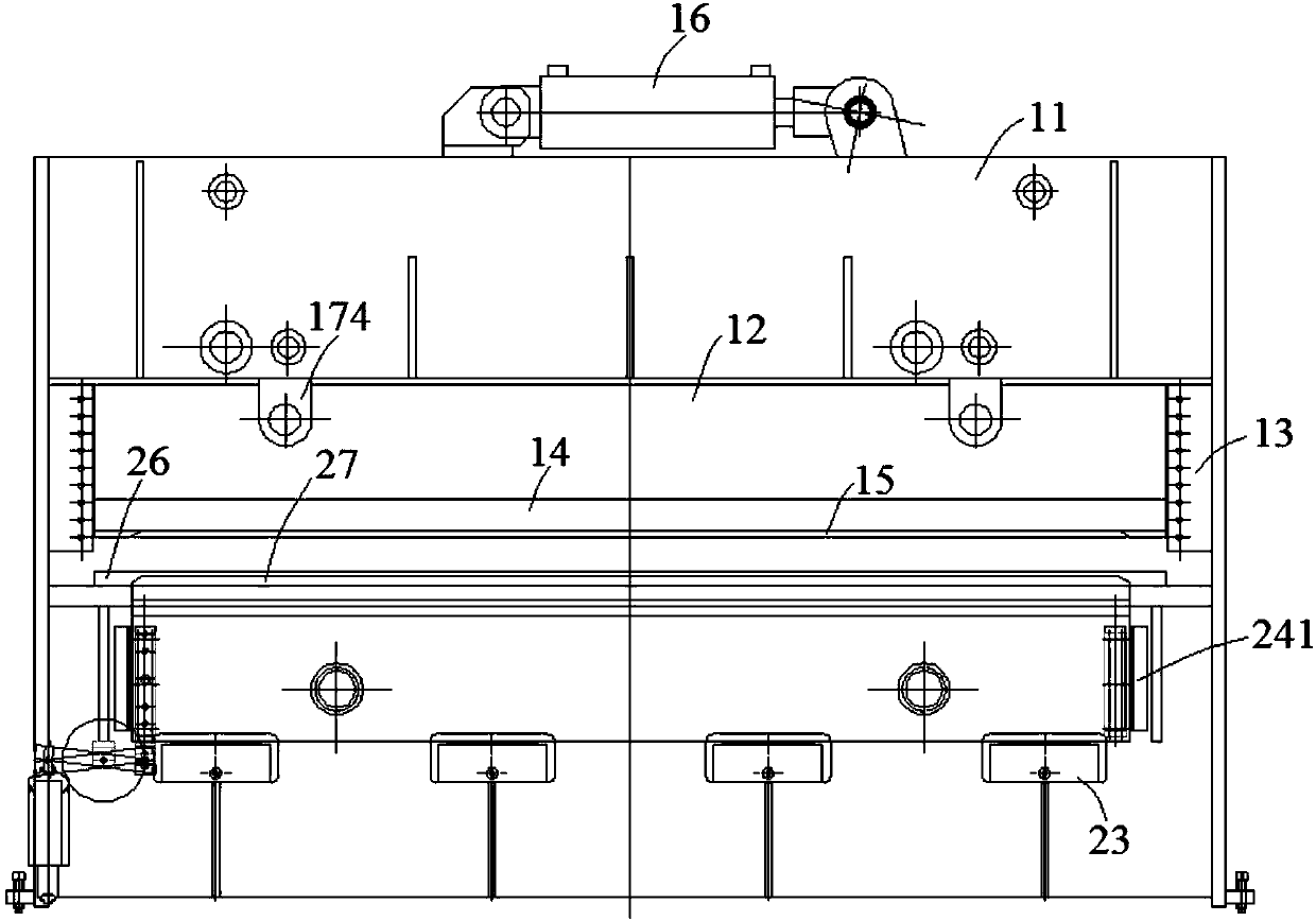
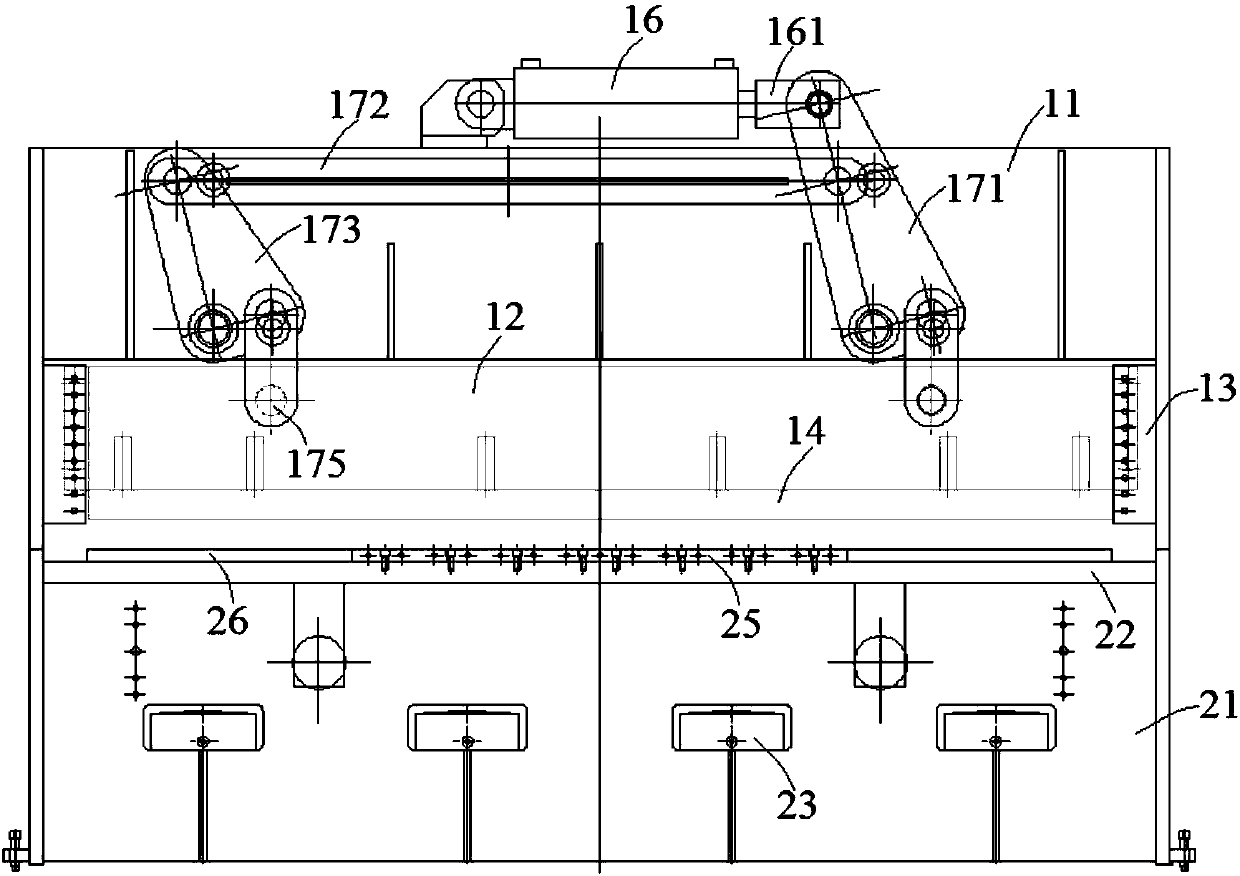
[0037] Combine figure 1 with image 3 , A low-cost container roof hydraulic forming system of this embodiment includes an upper box body 11, an upper slide block 12, an upper mold 15, an upper main cylinder 16, a lower box body 21, a lower main cylinder 23, a lower slide block 24 and Lower mold 27. The upper master cylinder 16 is arranged on the upper part of the upper box body 11, the upper sliding block 12 is arranged on the lower part of the upper box body 11, the bottom of the upper sliding block 12 is arranged with an upper mold base 14, and the upper mold 15 is fixed on the upper mold base 14.

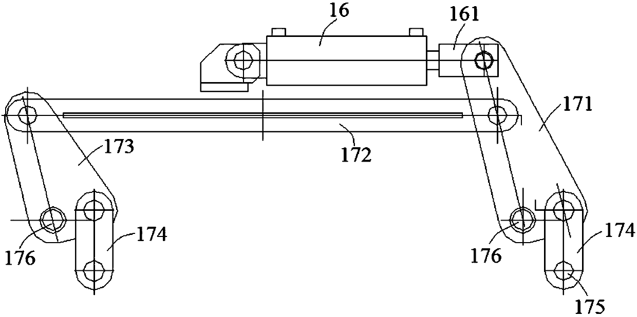
[0038] A drive unit is provided between the upper main cylinder 16 and the upper sliding block 12, which combines figure 2 The driving unit includes a main swing rod 171, a cross beam 172, an auxiliary swing rod 173 and a vertical link 174. One end of the cross beam 172 is axially connected with the main swing rod 171, and the other end is axially connected with the auxiliary swing...

Embodiment 2

[0043] Combine Figure 5 , Image 6 , Figure 7 with Picture 8 A low-cost container roof hydroforming system of this embodiment is basically the same as Embodiment 1, and the difference is that this embodiment further optimizes the design of the upper mold 15, the lower mold 27 and the blank holder 26, specifically: The upper mold 15 is set as a female mold, and threaded holes are arranged around the cavity of the female mold. The female mold is inserted into the threaded holes by bolts and is connected to the upper mold base 14 at the lower part of the upper sliding block 12. The lower mold 27 is a convex mold, and threaded holes are provided along the length direction of the lower mold 27, and the lower mold 27 is inserted into the threaded holes by bolts to be connected to the lower sliding block 24. The upper mold 15, the blank holder 26 and the lower mold 27 are all designed with a large arc structure along the length direction.

[0044] It is worth noting that in the init...

Embodiment 3

[0046] The low-cost container roof hydraulic forming system of this embodiment is basically the same as that of the second embodiment. The difference is that the thickness L1 at the highest point of the large arc surface in the longitudinal direction of the blank holder 26 in this embodiment is the same as the thickness at the lowest point. The difference in L2 is 14.2 mm. The thickness difference L3 between the highest point and the lowest point of the small arc surface of the blank holder 26 in the width direction is 3.5 mm.


PUM


Abstract

The invention discloses a low-cost container top plate hydraulic forming system and belongs to the field of hydraulic forming. The system comprises an upper box body, upper sliding blocks, upper molds, an upper main oil cylinder, a lower box body, lower main oil cylinders, lower sliding blocks and lower molds. The upper main oil cylinder is arranged at the upper part of the upper box body, and theupper sliding blocks are arranged at the lower part of the upper box body; the upper molds are fixed at the bottom of the upper sliding blocks, and a driving unit is arranged between the upper main oil cylinder and the upper sliding blocks; the upper main oil cylinder drives the upper sliding blocks to move in a vertical direction through the driving unit; and the lower sliding blocks are arranged in the lower box body, the lower portions of the lower sliding blocks are connected with the lower main oil cylinders, the upper portions of the lower sliding blocks are connected with the lower molds, and the lower main oil cylinders drive the lower sliding blocks to move in the vertical direction. The low-cost container top plate hydraulic forming system relates to a special machine designed for a container top plate structure, the cost of equipment purchasing is greatly reduced, and the economic burden of a small-and-medium-sized container top plate production enterprise is reduced.

Description

Technical field [0001] The invention relates to the technical field of hydraulic presses, and more specifically, to a low-cost container roof hydraulic forming system. Background technique [0002] As a general-purpose transportation tool, containers have played a great role in the existing logistics industry. At present, the commonly used container roofs generally adopt blind wave roofs. For specific structures, see Picture 9 A plurality of blind waves 31 are arranged on the container roof 3, and the blind waves 31 are configured to protrude upward from the container roof 3 and are closed on all sides. The blind waves 31 of the container roof 3 are integrally formed. The hydraulic press is an important forming equipment. The hydraulic pump is driven by an electric motor to produce high-pressure liquid, and the hydraulic cylinder generates linear motion to work. Due to the wide adaptability of hydraulic machining, it is widely used in metal and non-metal forming. At present, f...

Claims


Application Information

Patent Timeline
Patent Type & Authority Applications(China)
IPC IPC(8): B21D13/02B21D37/10B21D43/00B30B1/34
CPCB21D13/02B21D37/10B21D43/003B30B1/34
Inventor 王大进王启岗
Owner 安徽金大进重工机床有限公司
Why Eureka
Try Eureka