Vehicle power take-off system and method

A technology for vehicles and power take-offs, applied to vehicle components, control devices, auxiliary drive devices, etc., can solve problems such as limited power take-off input torque, poor power take-off effect, and the diameter of the input shaft of the power take-off cannot be too large. The effect of saving vehicle space and reducing vehicle cost

Pending Publication Date: 2018-04-20
SHAANXI FAST AUTO DRIVE GROUP CO LTD
View PDF0 Cites 8 Cited by
  • Summary
  • Abstract
  • Description
  • Claims
  • Application Information

AI Technical Summary

Problems solved by technology

[0008] Most of the power take-offs are through-shaft rear power take-offs, and the input shaft of the power take-off obtains power through spline connection with the transmission intermediate shaft. However, due to the structural limitations of the transmission, the shaft diameter of the transmission intermediate shaft determines the The diameter cannot be too large, so the maximum input torque is less than 600Nm, the power take-off input torque is limited, and the power take-off effect is poor

Method used


Image

  • Vehicle power take-off system and method

Examples


Embodiment Construction

[0033] The present invention will be further described in detail below in conjunction with the accompanying drawings and embodiments.

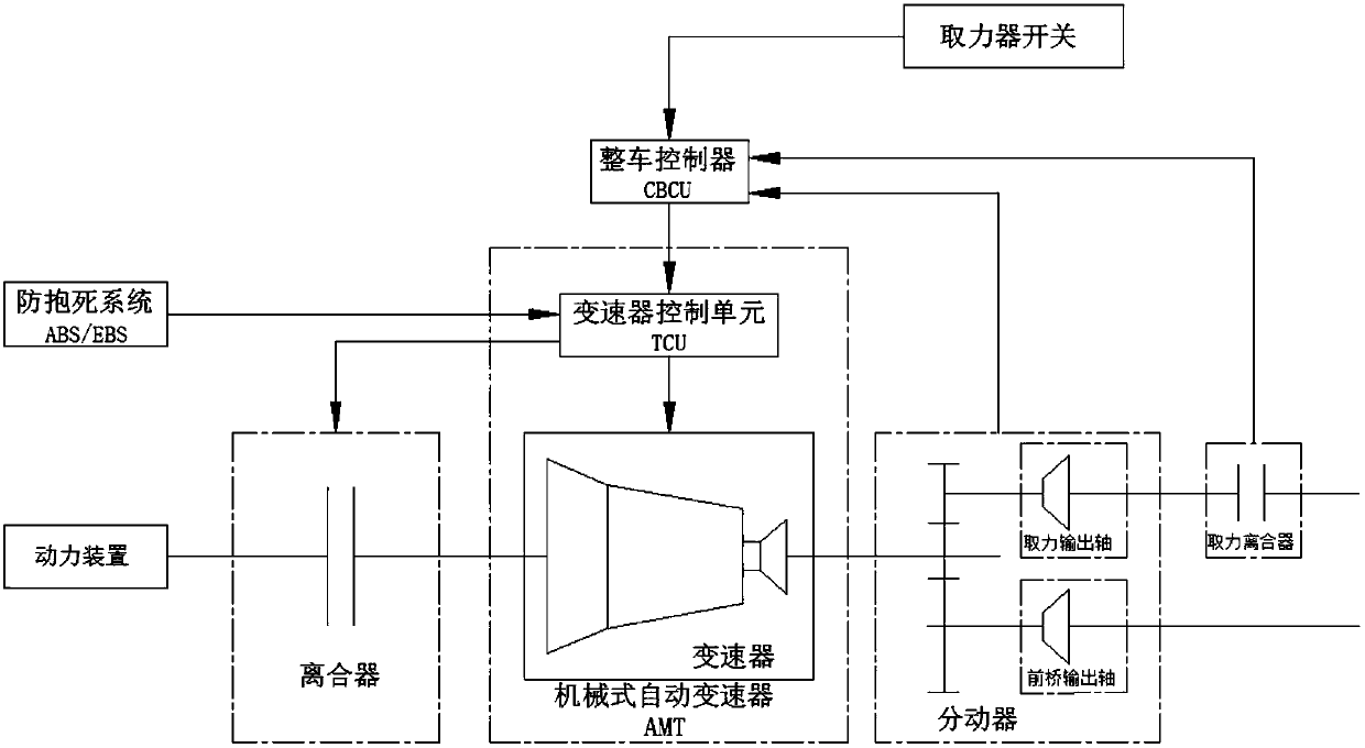
[0034] Such as figure 1 A vehicle power take-off system shown includes a power unit, a clutch, a mechanical automatic transmission, a transfer case, a power take-off clutch, a power take-off switch, a vehicle controller and an anti-lock braking system; the mechanical automatic transmission includes a mechanical The transmission body and the transmission control unit; the power unit, the clutch, the mechanical transmission body, the transfer case and the power take-off clutch are connected in sequence.

[0035] The pressure plate of the clutch is rigidly connected with the flywheel of the engine, and the driven plate of the clutch is connected with the input shaft of the mechanical automatic transmission through splines. The transmission control unit is connected to the anti-lock braking system and the vehicle controller through the CAN line; ...


PUM


Abstract

The invention relates to the technical field of engineering vehicle, particularly to a vehicle power take-off system and method. The vehicle power take-off system aims at achieving a power take-off function on the basis of only equipping a retarder without a power take-off. The vehicle power take-off system comprises a power device, a clutch, a mechanical automatic gearbox, a transfer case, a power take-off clutch, a power take-off switch, a vehicle control unit and an anti-lock system, wherein the mechanical automatic gearbox comprises a mechanical gearbox body and a gearbox control unit; thetransfer case comprises a front axle output shaft and a power take-off output shaft and controls to transmit disconnecting signals or connecting signals of the front axle output shaft; the power take-off clutch transmits disconnecting signals and connecting signals of the power take-off output shaft; the power take-off switch transmits power take-off signals or power take-off stopping signals tothe vehicle control unit; the vehicle control unit receives the disconnecting signals or the connecting signals of the power take-off output shaft, the disconnecting signals or the connecting signalsof the front axle output shaft, and the power take-off signals or the power take-off stopping signals, and transmits the power take-off signals or the power take-off stopping signals to the gearbox control unit.

Description

technical field [0001] The invention relates to the technical field of engineering vehicles, in particular to a vehicle power take-off system and a power take-off method. Background technique [0002] Currently, high-end construction vehicles can weigh up to 130 tons and are usually equipped with a transfer case, retarder and / or power take-off. [0003] The function of the transfer case is to distribute the power output by the transmission to each drive axle and further increase the torque. The transfer case is also a gear transmission system, which is fixed on the frame alone, and its output shaft is connected with the output shaft of the transmission with a universal transmission. There are several output shafts of the transfer case, which are connected to each The drive axle is connected. [0004] The retarder plays the role of smooth deceleration when the car decelerates or goes down a long slope, avoiding the wear and heat caused by the use of brakes. [0005] A powe...

Claims


Application Information

Patent Timeline
IPC IPC(8): B60K25/06
CPCB60K25/06
Inventor 韩晓宇
Owner SHAANXI FAST AUTO DRIVE GROUP CO LTD
Why Eureka
Try Eureka