Yarn conveying device

A technology of yarn feeding device and mounting frame, which is applied in the direction of textiles and papermaking, weft knitting, knitting, etc. It can solve the problems of large processing error, low surface dimensional accuracy, low surface hardness, etc., and achieves convenient assembly and maintenance. The effect of low requirements and low production costs

Active Publication Date: 2018-04-20
CIXI SUN TEXTILE SCI & TECH
View PDF7 Cites 1 Cited by
  • Summary
  • Abstract
  • Description
  • Claims
  • Application Information

AI Technical Summary

Problems solved by technology

[0003] The yarn feeding wheel includes the following types, one is a plastic casing, and a metal rod or a ceramic rod is installed on the yarn feeding surface of the casing to convey the yarn. The disadvantage is that the plastic casing has a short service life and the rear Metal rods or ceramic rods are not only complex in structure, but also have low dimensional accuracy. In addition, the plastic shell has large processing errors due to injection molding, resulting in large processing errors after assembly of the yarn feeding wheel; the other is currently widely used in the market. The whole is a metal shell, the surface is hard oxidized or the surface is sprayed with hard chromium plating layer or sprayed with ceramic layer. The advantage of surface hard oxidation is that the connection strength between the surface layer and the metal shell is high, and the surface dimensional accuracy is high. The disadvantage is the surface hardness. Low; the advantage of spraying the hard chromium layer on the surface is the high precision of the surface size, and its disadvantage is that the connection strength between the surface layer and the metal shell is low, and the surface hardness is low; the advantage of spraying the ceramic layer on the surface is that the surface hardness is high, and the disadvantage is the connection of the ceramic layer Low strength and low surface dimensional accuracy
The common problem of the existing yarn delivery wheel is that after using for a period of time, yarn wadding and other sundries will accumulate between the yarn delivery wheel and the dust cover, making the rotation of the yarn delivery wheel inflexible, resulting in the friction on the transmission wheel that drives it to rotate. The force on the transmission belt increases, which makes the transmission belt more worn. In severe cases, the transmission belt cannot drive the transmission wheel to rotate, and there is a slipping phenomenon between the transmission wheel and the transmission wheel, so that the yarn feeder cannot convey the yarn.
In order not to affect the normal rotation of the yarn delivery wheel, it is necessary to regularly clean up the yarn wadding and other sundries in the yarn delivery wheel. The current cleaning method is to disassemble the yarn delivery device and remove the yarn delivery wheel from the main shaft for cleaning, which is time-consuming and laborious.

Method used


Image

  • Yarn conveying device
  • Yarn conveying device
  • Yarn conveying device

Examples


Embodiment Construction

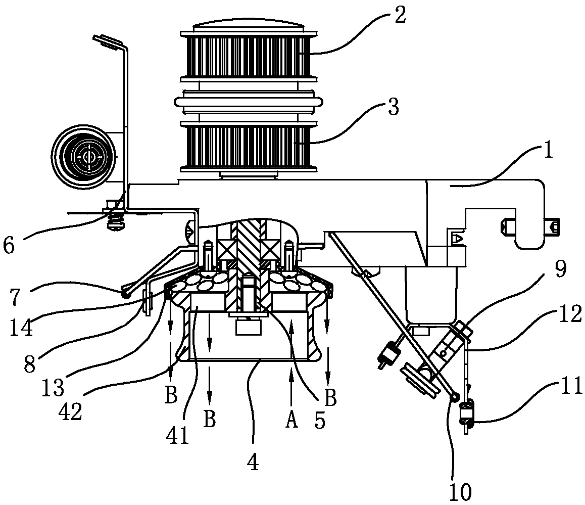
[0013] Combine below figure 1 , figure 2 and image 3 The present invention is further described.

[0014] like figure 1 , figure 2 and image 3 The yarn feeding device shown includes a housing 1 and a transmission pulley 2, a clutch 3, a main shaft 5, a wire feeding wheel 4, a dust cover 13, a lead frame 6, a front detection rod 7, and a yarn feeding device arranged on the housing 1. Ceramic ring 8, yarn output assembly and rear detection rod 10.

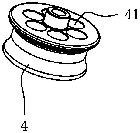
[0015] The dustproof cover 13 is installed on the bottom of the housing 1, and the dustproof cover 13 is above the wire feeding wheel 4. The yarn feeding wheel 4 is an aluminum wheel body, and the top of the aluminum wheel body is provided with a cleaning hole 41. The cleaning holes 41 are multiple One, with the main shaft 5 as the center regular arrangement, when the main shaft 5 can be made to rotate, the line transmission wheel rotates smoothly. The cleaning hole 41 not only reduces the weight of the yarn delivery wheel...


PUM


Abstract

The invention relates to the field of fittings of a weaving machine. A yarn conveying device comprises a shell and a transmission belt wheel, a main shaft, a thread conveying wheel, a dust preventioncover, a thread guide rack, a yarn feeding porcelain ring and a yarn discharging assembly which are arranged on the shell, a cleaning hole is formed in the top of an aluminum-made wheel body, and a micro-arc oxidation ceramic layer which is integrally connected with the aluminum-made wheel body is arranged on the outer surface of the aluminum-made wheel body; the yarn discharging assembly comprises a mounting rack, a yarn clamping machine and two yarn discharging porcelain rings, wherein the yarn clamping machine and the yarn discharging porcelain rings are fixed on the mounting rack. The yarnconveying device has the advantages that the service life is long, the yarn clamping machine is convenient to assemble and maintain, foreign materials, such as yarn floccules, in a yarn conveying wheel is convenient to remove, and the production cost is low.

Description

technical field [0001] The invention relates to the field of accessories for looms. Background technique [0002] Yarn feeding device is an important part of the loom, which includes the casing and the drive pulley, clutch, main shaft, wire feeding wheel, dust cover, lead frame, front detection rod, yarn feeding ceramic ring, and yarn gripper set on the casing. , Yarn output ceramic ring and rear detection rod; the transmission pulley and clutch are set above the casing, the wire transmission wheel is set under the casing, the dust cover is installed above the transmission pulley, and the upper part of the main shaft is connected with the transmission pulley and clutch. The lower part of the main shaft is connected with the yarn feeding wheel, and the lead frame, the yarn feeding ceramic ring, the yarn gripper and the yarn discharging ceramic ring are arranged on the casing. When working, the transmission belt on the knitting machine drives the transmission pulley on the up...

Claims


Application Information

Patent Timeline
Patent Type & Authority Applications(China)
IPC IPC(8): D04B15/38D04B27/10D04B35/32
CPCD04B15/38D04B27/10D04B35/32
Inventor 高山高峰周定安
Owner CIXI SUN TEXTILE SCI & TECH
Why Eureka
Try Eureka