Energy consumption device and anti-collision facility

An energy-consuming device and end plate technology, applied in road safety devices, anti-vibration, roads, etc., can solve the complex design, construction and maintenance work of pier anti-collision facilities, the inability to customize the design and manufacture of anti-collision facilities, and the difficult anti-collision facilities. and other problems, to achieve stable and reliable energy absorption and energy absorption, reduce engineering costs, and achieve small fluctuations in compressive stiffness.

Active Publication Date: 2018-04-20
CHINA MAJOR BRIDGE ENERGINEERING
View PDF9 Cites 0 Cited by
  • Summary
  • Abstract
  • Description
  • Claims
  • Application Information

AI Technical Summary

Problems solved by technology

[0003] Due to the different probabilities of being hit by different parts of the building, and the damage areas caused by vehicles or boats of different tonnages are different, the existing anti-collision facilities cannot be precisely customized and manufactured according to the anti-collision requirements of different buildings
Taking the anti-collision facilities of bridge piers as an example, the existing anti-collision facilities of bridge piers include inner steel ring and outer steel ring surrounding the bridge pier, and a large number of energy-dissipating devices such as sealing air cushions or steel rings are arranged between the inner steel ring and the outer steel ring. Absorbing impact energy, because each individual air cushion or steel traveler has great differences in shape, structure, performance, etc., and on-site construction is prone to installation errors, which not only makes it difficult for technicians to obtain anti-collision facilities through accurate structural design analysis Reliable data on local and overall energy absorption and consumption, and the inability to effectively utilize a single energy-consuming device to achieve modular design and manufacture, which makes the design, construction and maintenance of existing bridge pier anti-collision facilities complicated and high in construction costs

Method used


Image

  • Energy consumption device and anti-collision facility
  • Energy consumption device and anti-collision facility
  • Energy consumption device and anti-collision facility

Examples


Embodiment Construction

[0031] The present invention will be further described in detail below in conjunction with the accompanying drawings and specific embodiments.

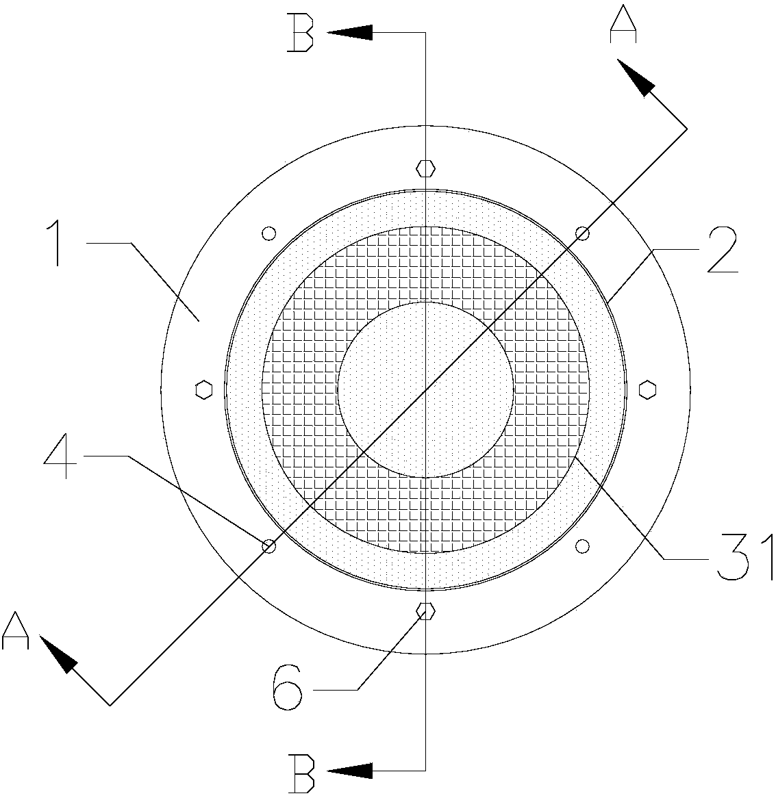
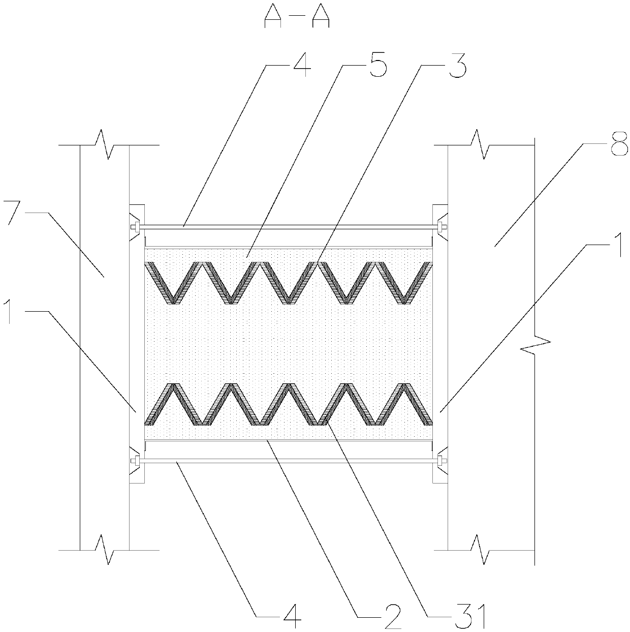
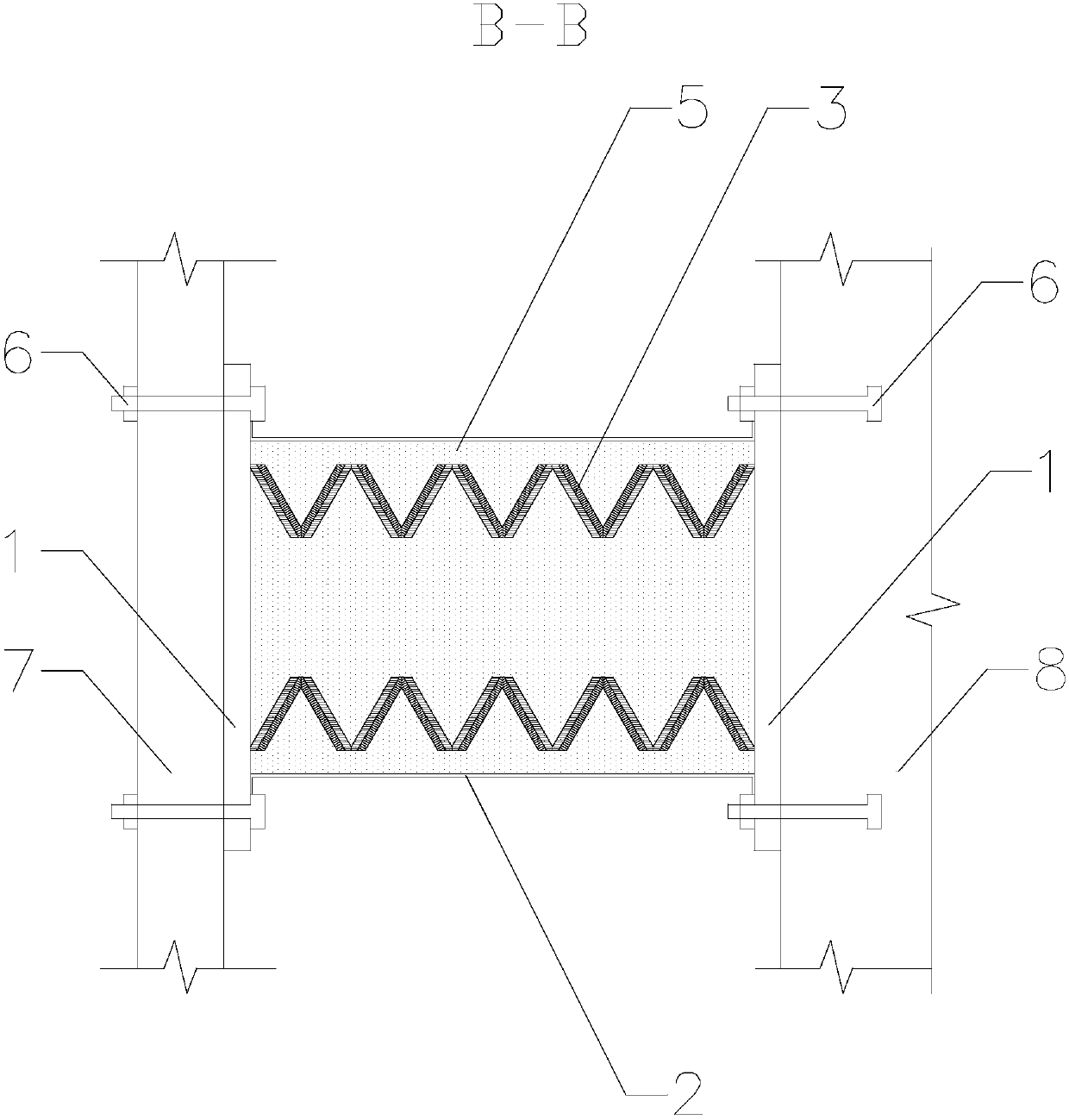
[0032] see figure 1 with figure 2 shown, for clarity, figure 1 One end plate of the energy dissipation device is removed. An embodiment of the present invention provides an energy dissipation device. The energy dissipation device includes two end plates 1, a flexible sheath 2, a deformable component 3 and a pressing component 4. The flexible sheath The sleeve 2 and the pressing assembly 4 are located between the two end plates 1 , the deformable assembly 3 is arranged inside the flexible sheath 2 , and the pressing assembly 4 is arranged outside the flexible sheath 2 .

[0033] The flexible sheath 2 is a hollow cylindrical body with openings at both ends. The flexible sheath 2 can be made of rubber or other materials. The openings at both ends of the flexible sheath 2 are fixedly connected with the two end plates 1 by bolts.

[00...


PUM


Abstract

The invention discloses an energy consumption device and an anti-collision facility, and relates to the technical field of building protection. The energy consumption device comprises two end plates,a flexible sheath, a deformable component and a compressing component, wherein the flexible sheath is a hollow cylinder provided with openings in two ends, and the openings in the two ends of the flexible sheath are fixedly connected with the two end plates; openings in two ends of the deformable component are respectively butted with the two end plates, and the deformable component comprises at least one thin-walled metallic tapered pipe which is arranged in an inner cavity of the hollow cylinder; and the compressing component is arranged outside the flexible sheath, two ends of the compressing component are fixedly connected with the two end plates, and the compressing component is used for oppositely compressing the two end plates. According to the structure of the thin-walled metallictapered pipes, deformable mechanical performance indexes of the thin-walled metallic tapered pipes can be obtained; aiming at energy absorption and energy consumption requirements in actual collision,the quantity and stacking sequence of the thin-walled metallic tapered pipes in each energy consumption device can be determined; and by virtue of structural design and analysis, accurate and reliable energy absorption and energy consumption data can be obtained, thereby realizing accurate design and manufacture of the energy consumption device.

Description

technical field [0001] The invention relates to the technical field of building protection engineering, in particular to an energy consumption device and an anti-collision facility. Background technique [0002] With the rapid development of traffic in our country, the number of roads and bridges has been increasing, and the safety problems of buildings and bridges on both sides of the road have become increasingly prominent, for example, accidents where vehicles hit buildings on both sides of the road or on bridges , and buildings near the waterway (such as bridge piers) may be damaged due to ship impact. Safety of ships and buildings. [0003] Since different parts of the building have different impact probabilities, and the damage areas caused by vehicles or boats of different tonnages are different, the existing anti-collision facilities cannot be precisely customized for the anti-collision requirements of different buildings. Design and manufacture. Taking the anti-co...

Claims


Application Information

Patent Timeline
Patent Type & Authority Applications(China)
IPC IPC(8): E01F15/14E04B1/98
CPCE01F15/14E04B1/98
Inventor 贾恩实苏传海詹昊庄勇马润平梅大鹏
Owner CHINA MAJOR BRIDGE ENERGINEERING
Why Eureka
Try Eureka