Jet device, spray head assembly and concrete jet vehicle

A technology of injection device and assembly, which is used in vertical shaft equipment, earth-moving drilling, wellbore lining, etc., can solve the problems of short service life and easy bursting of nozzle joints, avoid explosion, ensure mixing, and avoid nozzle explosion Effect

Inactive Publication Date: 2018-04-20
HUNAN PENGXIANG XINGTONG AUTOMOBILE CO LTD
View PDF9 Cites 5 Cited by
  • Summary
  • Abstract
  • Description
  • Claims
  • Application Information

AI Technical Summary

Problems solved by technology

[0005] The first object of the present invention is to provide a spraying device, which solves the technical problems of easy bursting of the nozzle connection and short service life in the prior art

Method used


Image

  • Jet device, spray head assembly and concrete jet vehicle
  • Jet device, spray head assembly and concrete jet vehicle
  • Jet device, spray head assembly and concrete jet vehicle

Examples


Embodiment 1

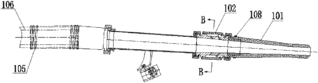
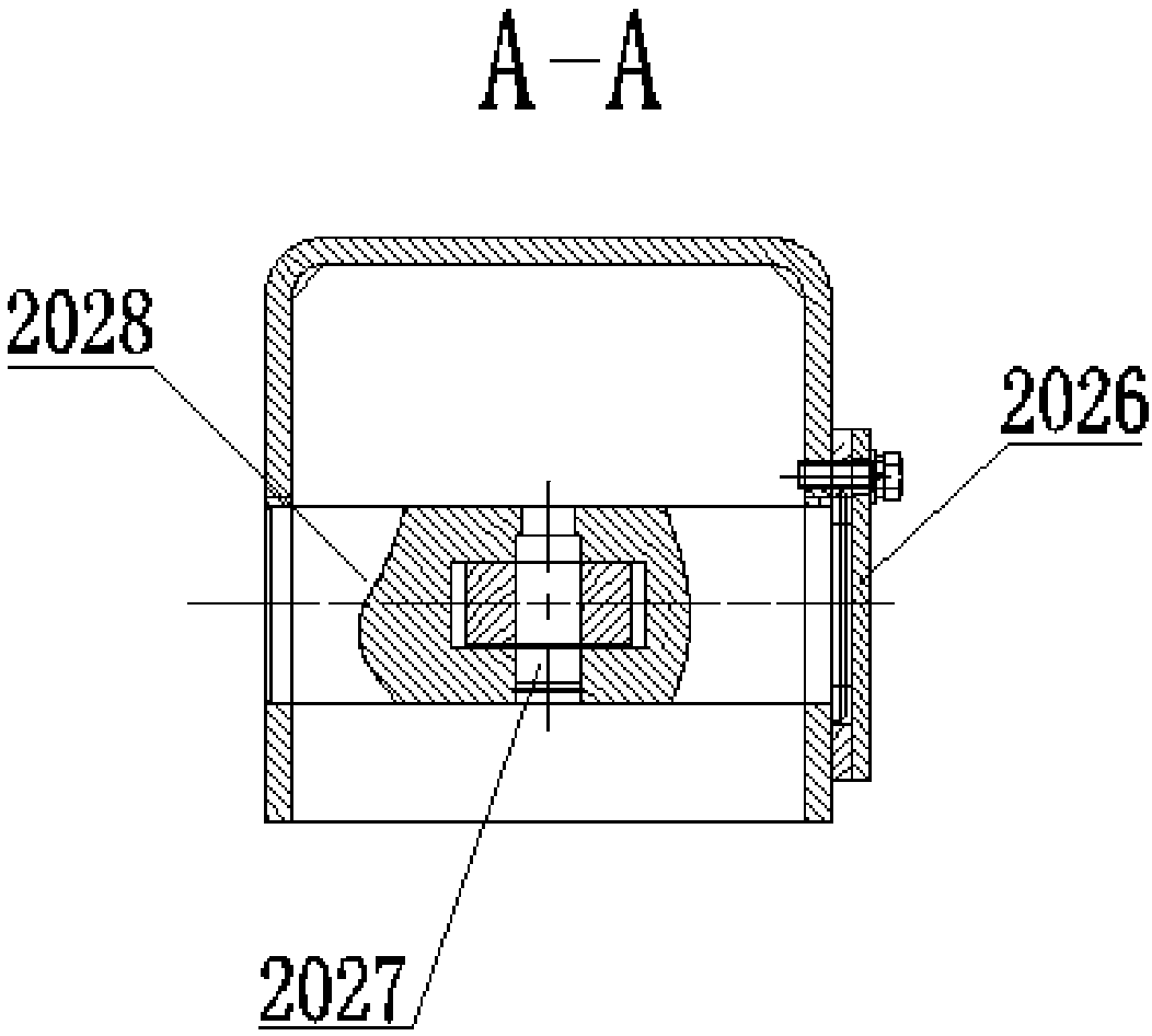
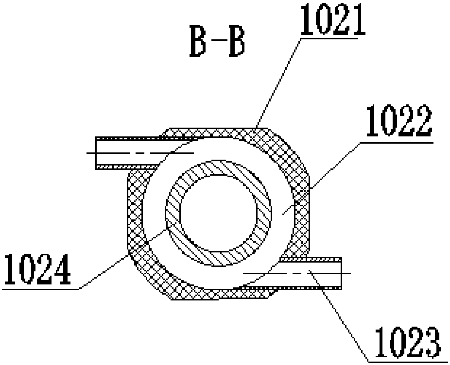
[0042] figure 1 Schematic diagram of the structure of the injection device provided for the embodiment of the present invention; figure 2 A cross-sectional view of A-A of the injection device provided for the embodiment of the present invention; image 3 B-B sectional view of the injection device provided by the embodiment of the present invention.

[0043] like Figure 1-3 As shown, the injection device provided in this embodiment includes: a nozzle 101 and a mixing device 102 connected to the nozzle 101, and a clamping device 108 for clamping the nozzle 101 is provided at the connection between the mixing device 102 and the nozzle 101; the mixing device 102 includes The casing 1021 and the mixer 1024, the cavity 1022 is formed between the casing 1021 and the mixer 1024; the ventilation pipe 1023 is connected to the casing 1021; the problem of the nozzle 101 bursting is avoided; the construction interval is reduced, and the life of the nozzle 101 is improved And greatly r...

Embodiment 2

[0052] Figure 4 Schematic diagram of the structure of the nozzle assembly provided by the embodiment of the present invention; Figure 5 Schematic diagram of the structure of the driving device of the spray head assembly provided by the embodiment of the present invention.

[0053] like Figure 4-5 As shown, the spray head assembly provided in this embodiment includes: a driving device and the above-mentioned spraying device 100 ; the driving device is connected to the outer wall of the mixing device 102 on the spraying device 100 .

[0054] Specifically, the driving device includes a swinging device 201 and a brushing device 202; the brushing device 202 includes a first hanger 2021 and a second hanger 2022, the first hanger 2021 is connected to the swinging device 201, and the second hanger 2022 is connected by The parts are connected to the outer wall of the mixing device 102.

[0055] Further, the brushing device 202 also includes a first output mechanism 2024 installed...

Embodiment 3

[0065] The concrete spraying vehicle provided in this embodiment includes: the above-mentioned spray head assembly.


PUM


Abstract

The invention relates to the technical field of concrete construction, in particular to a jet device, a spray head assembly and a concrete jet vehicle. The jet device comprises a jet nozzle and a mixing device connected with the jet nozzle, and a clamping device for tightly clamping the jet nozzle is arranged at the position where the mixing device is connected with the jet nozzle. The mixing device comprises a casing pipe and a mixer, and a cavity is formed between the casing pipe and the mixer. A ventilation pipe is connected to the casing pipe. The spray head assembly comprises a driving device and the jet device, the driving device is connected with the outer wall of the mixing device on the jet device, and the driving device comprises a swinging device and a brushing device. The brushing device comprises a first hanging bracket and a second hanging bracket, the first hanging bracket is connected with the swinging device, and the second hanging bracket is connected with the outer wall of the mixing device through a connection part. The concrete jet vehicle comprises the spray head assembly. The technical problems that a spray head in the prior art is prone to cracking, and theservice life is short are solved.

Description

technical field [0001] The invention relates to the technical field of concrete construction, in particular to a spraying device, a spray head assembly and a concrete spraying vehicle. Background technique [0002] Concrete spraying machine is a construction machinery equipment that uses compressed air to continuously transport concrete mixture and sprays it onto the spraying surface to form a supporting structure and strengthen and protect the surface of the building. At present, the commonly used concrete sprayers are dry concrete sprayer and wet concrete sprayer. Among them, the wet concrete spraying machine has been widely used because of its small concrete rebound, low dust content in the air, and low harm to the human body. The nozzle assembly of the existing wet concrete sprayer usually adjusts the position of the nozzle assembly according to the spray surface, and sprays the spray surface continuously after the position is determined, and then moves the nozzle assem...

Claims


Application Information

Patent Timeline
Patent Type & Authority Applications(China)
IPC IPC(8): E04G21/04E21D11/10
CPCE21D11/105E04G21/04E04G2021/049
Inventor 胡鹏填魏鹏程
Owner HUNAN PENGXIANG XINGTONG AUTOMOBILE CO LTD
Why Eureka
Try Eureka