Microscopic rock network model manufacturing method

A technology of network model and production method, which is applied in earth-moving drilling, wellbore/well components, etc., can solve problems such as differences in oil and gas flow states, failure to observe fluid flow in observation channels, adsorption, diffusion, and large size differences.

Active Publication Date: 2018-04-20
CHINA UNIV OF PETROLEUM (BEIJING)
View PDF6 Cites 16 Cited by
  • Summary
  • Abstract
  • Description
  • Claims
  • Application Information

AI Technical Summary

Problems solved by technology

[0004] However, the past microscopic glass models have great limitations when applied to the development of tight reservoirs, mainly in four aspects: (1) The channel scale of the conventional etching sand filling model is generally too large, generally 20 μm-200 μm, which is different from that of tight reservoirs. The size of the main pore throats in the reservoir varies greatly (pores 20μm-80μm, throats 100nm-700nm) and it is difficult to study the flow of fluids in micro-nanoscale pore throats; (2) Conventional visual microfluidic chips are all two-dimensional chips , the channel depth of the entire model is the same, which is very different from the three-dimensional difference between the pore throats of real sandstones. The microscopic dynamics such as the Haynes step and oil-water accumulation of fluid flowing between the pore throats are difficult to appear, which is different from that of oil and gas in tight oil reservoirs. (3) For the microscopic model made of real sandstone slices as raw materials, adhesives need to be added during the production process to change the surface properties of the core, and the observation effect is poor, and the fluid inside the observation channel cannot be reached. The purpose of flow, adsorption, and diffusion

Method used


Image

  • Microscopic rock network model manufacturing method
  • Microscopic rock network model manufacturing method
  • Microscopic rock network model manufacturing method

Examples


Embodiment 1

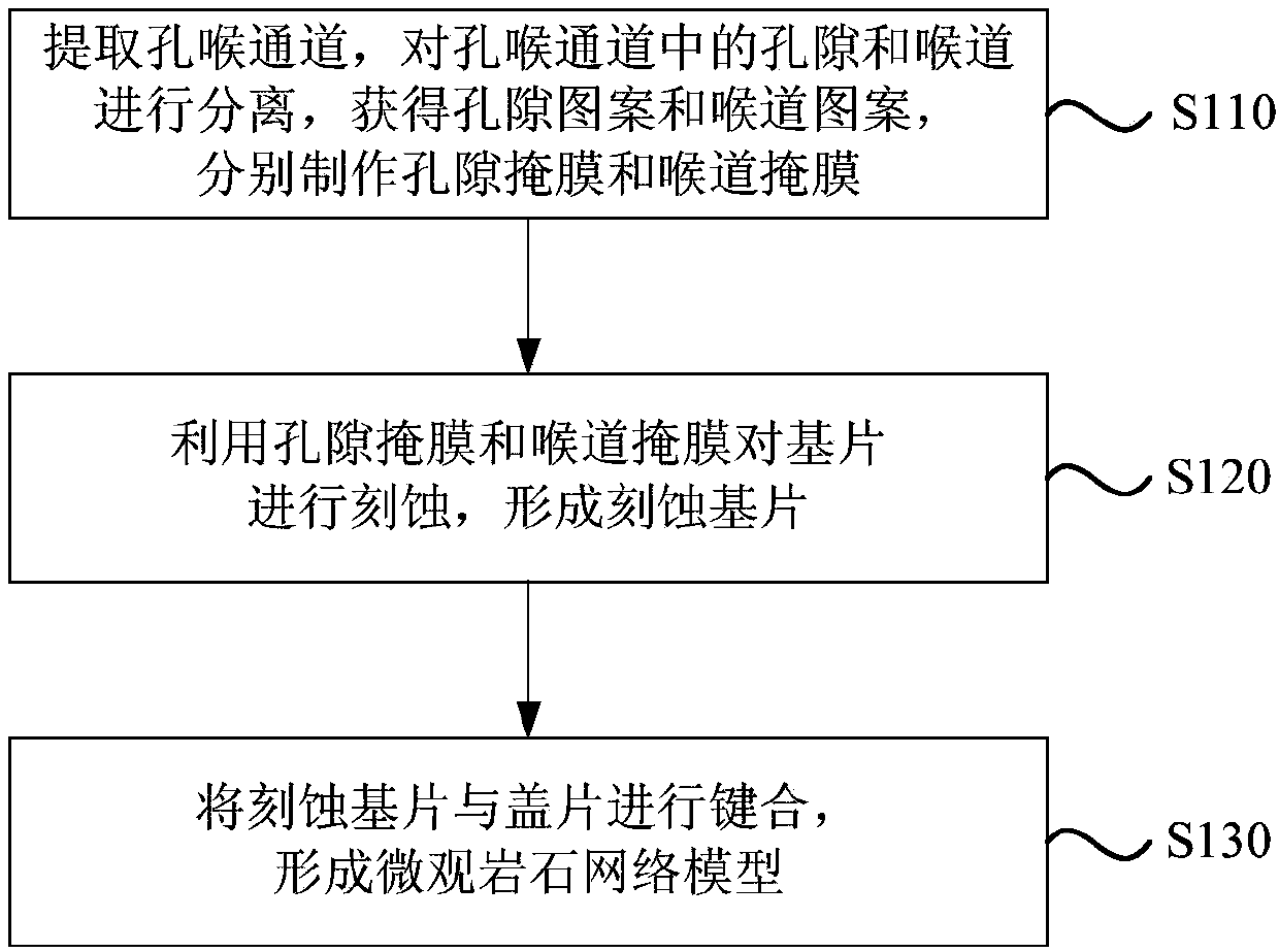
[0058] figure 1It is a flowchart of a method for making a microscopic rock network model provided by Embodiment 1 of the present invention. This embodiment is applicable to the production of a microscopic model of tight oil reservoirs, and specifically includes the following steps:

[0059] Step 110, extracting pore-throat channels, separating pores and throats in the pore-throat channels, obtaining pore patterns and throat patterns, and making pore masks and throat masks respectively.

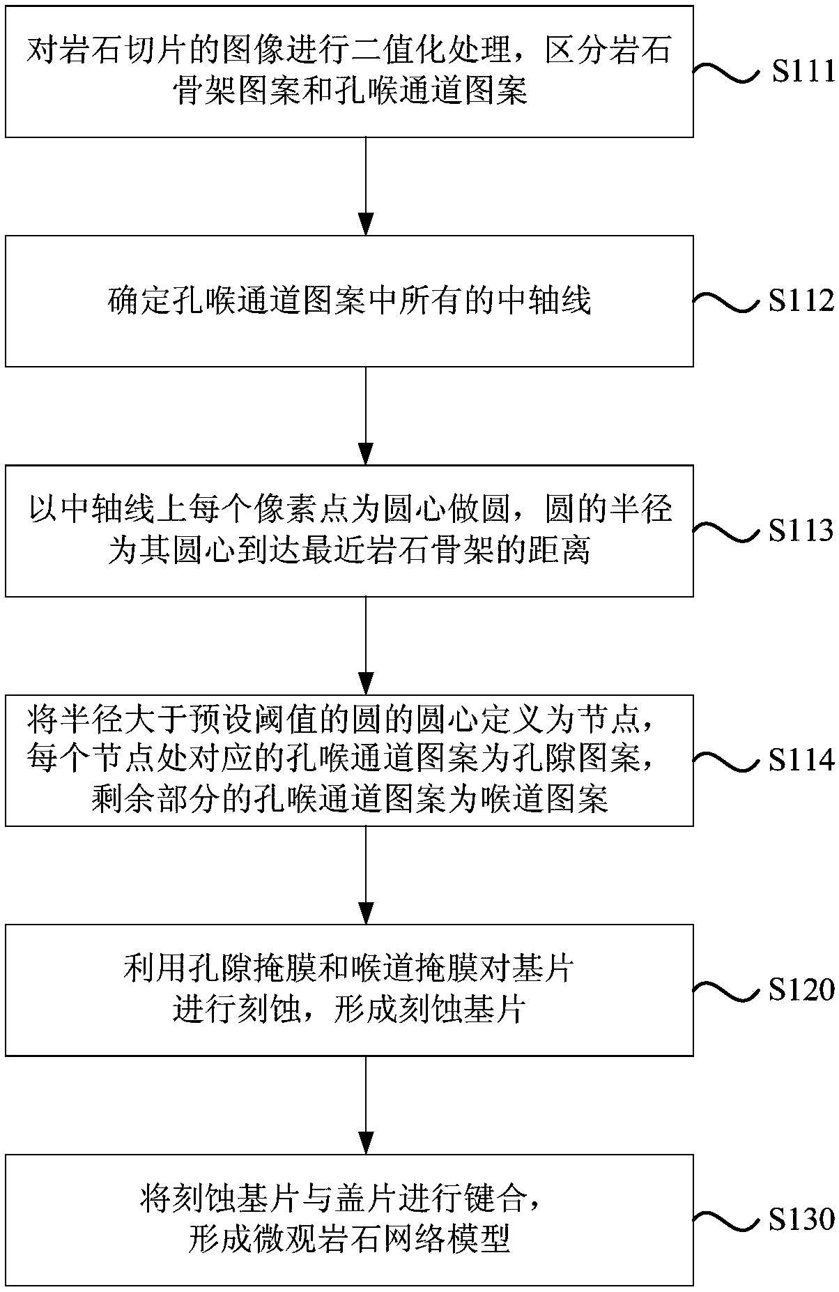
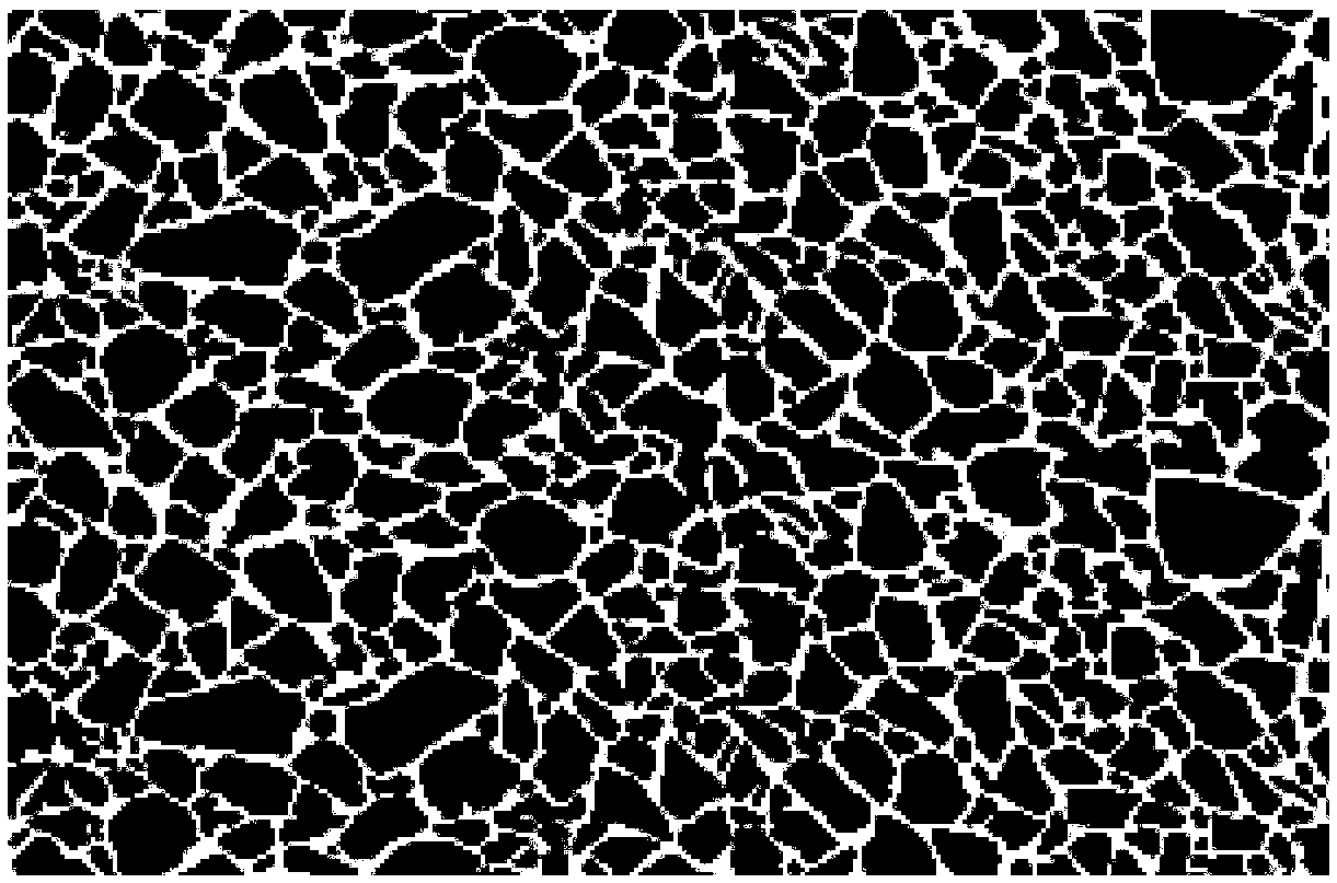
[0060] Among them, the extraction of pore-throat channels can be realized by using real sandstone castings, and thin slices of real sandstone castings are cut to form rock slices, and the rock skeleton area in the rock slice image is distinguished by binarizing the images of the rock slices and the pore-throat channel area, realize the extraction of pore-throat channels, and obtain the pattern composed of the pore area. In the pore-throat channel area, the area where the pore pattern is remove...

Embodiment 2

[0077] Figure 8 It is a flow chart of another method for making a microscopic rock network model provided in Embodiment 2 of the present invention, refer to Figure 8 , in the manufacturing method provided in this embodiment, S120, etching the substrate using the pore mask and the throat mask, specifically includes the following steps:

[0078] S121, pore etching, using a pore mask to etch the substrate to form a half-etched substrate;

[0079] Wherein, both the pore etching in this step and the throat etching in step S123 can be performed using a wet etching process, and a half-etched substrate with pores can be obtained through pore etching.

[0080] Preferably, the method of pore etching includes: stacking the pore mask and the substrate and exposing through an exposure machine, so that the pattern of the pore mask is transferred to the substrate; cleaning the photoresist on the substrate and exposing part; in an ultrasonic water bath environment, the substrate is immers...

Embodiment 3

[0096] Figure 10 It is a flow chart of another method for making a microscopic rock network model provided by Embodiment 3 of the present invention. refer to Figure 10 , in the manufacturing method provided in this embodiment, S130, bonding the etched substrate and the cover sheet to form a microscopic rock network model, specifically includes the following steps:

[0097] S131. Pretreating the etched substrate;

[0098] Among them, the pretreatment of the etched substrate includes boiling treatment and rinsing, first with H 2 SO 4 with H 2 o 2 Prepare the solution according to the ratio of 4:1 and boil the etched substrate and cover slip for 10-15 minutes, then rinse with petroleum ether and ethanol for 10 minutes to clean the etched substrate and cover slip, and petroleum ether can wash off the etched substrate and cover slip. Ethanol is used to wash away the inorganic substances adhering to the etched substrate and cover slip. Through the pretreatment of the etched...


PUM


Abstract

The invention discloses a microscopic rock network model manufacturing method. The microscopic rock network model manufacturing method comprises the steps that a pore-throat passage is extracted, pores and throat ways in the pore throat passage are separated, pore patterns and throat way patterns are obtained, and pore masks and throat way masks are manufactured correspondingly; through the pore masks and the throat way masks, base pieces are etched to form etched base pieces; and the etched base pieces are in key fit with cover pieces to form a microscopic rock network model. According to themicroscopic rock network model manufacturing method, through pore-throat separating, image aligning and repeated photoetching, a micro-nano oil gas flowing passage which is closer to the reality of an oil reservoir is achieved in the microscopic glass model, control over the reaction time in the etching technique is accurate, the depth-width ratio, smoothness and flatness of the passage are good,pressure does not need to be provided in the key fit process, the nano passage can be better protected, key fit of the real sand rock microscopic models of the micron pores and the nano throat ways is achieved, and microscopic dynamic change, such as Haines phase step and non-wetting phase coalescence, which cannot occur on a two-dimensional planar model is taken on.

Description

technical field [0001] The embodiments of the present invention relate to the field of oil and gas development, in particular to a method for making a microscopic rock network model. Background technique [0002] With the continuous deepening of theoretical research on oil and gas resource development, the hot and difficult issues in oil and gas field development have gradually shifted from conventional oil and gas development and enhanced oil recovery to unconventional oil and gas efficient development. [0003] my country's microscopic physical simulation experiments started relatively late. The seepage of the Chinese Academy of Sciences, led by Academician Guo Shangping, put forward the idea of ​​"microscopic seepage" earlier, and formed a series of microscopic seepage simulation and testing technologies in the 1990s. A large number of studies have been carried out on fluid flow in micron-scale channels in conventional oil reservoirs, revealing some important seepage mecha...

Claims


Application Information

Patent Timeline
Patent Type & Authority Applications(China)
IPC IPC(8): E21B49/00
CPCE21B49/00
Inventor 李俊键于馥玮姜汉桥李金鸿赵玉云范桢成宝洋沈康琦苏航
Owner CHINA UNIV OF PETROLEUM (BEIJING)
Why Eureka
Try Eureka