Oil way arranging structure of engine piston cooling nozzle

A piston cooling nozzle and layout structure technology, which is applied to the cooling of the engine, engine components, machines/engines, etc., can solve the problems of complex cylinder structure, difficult production and processing, etc., to simplify the cylinder structure, simplify casting, and ensure production Effects on Efficiency and Yield

Inactive Publication Date: 2018-04-20
CHONGQING CHANGAN AUTOMOBILE CO LTD
View PDF9 Cites 0 Cited by
  • Summary
  • Abstract
  • Description
  • Claims
  • Application Information

AI Technical Summary

Problems solved by technology

[0005] The cooling oil passages in the above two documents are all arranged inside the cylinder body, which leads to complex structure of the cylinder body and difficult production and processing. Therefore, it is necessary to improve the oil passage arrangement structure of the existing engine piston cooling nozzles

Method used


Image

  • Oil way arranging structure of engine piston cooling nozzle
  • Oil way arranging structure of engine piston cooling nozzle
  • Oil way arranging structure of engine piston cooling nozzle

Examples


Embodiment Construction

[0020] The present invention will be described in detail below in conjunction with the accompanying drawings and embodiments.

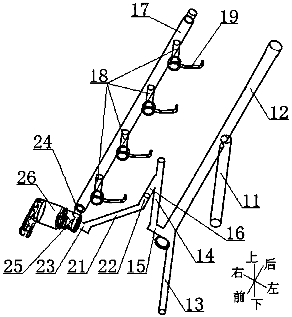
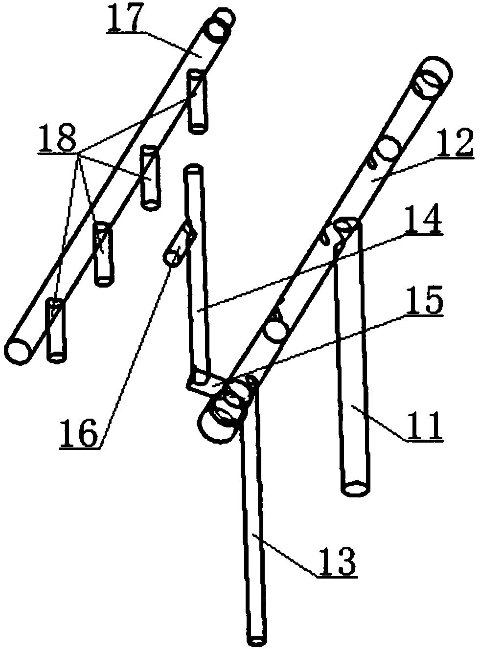
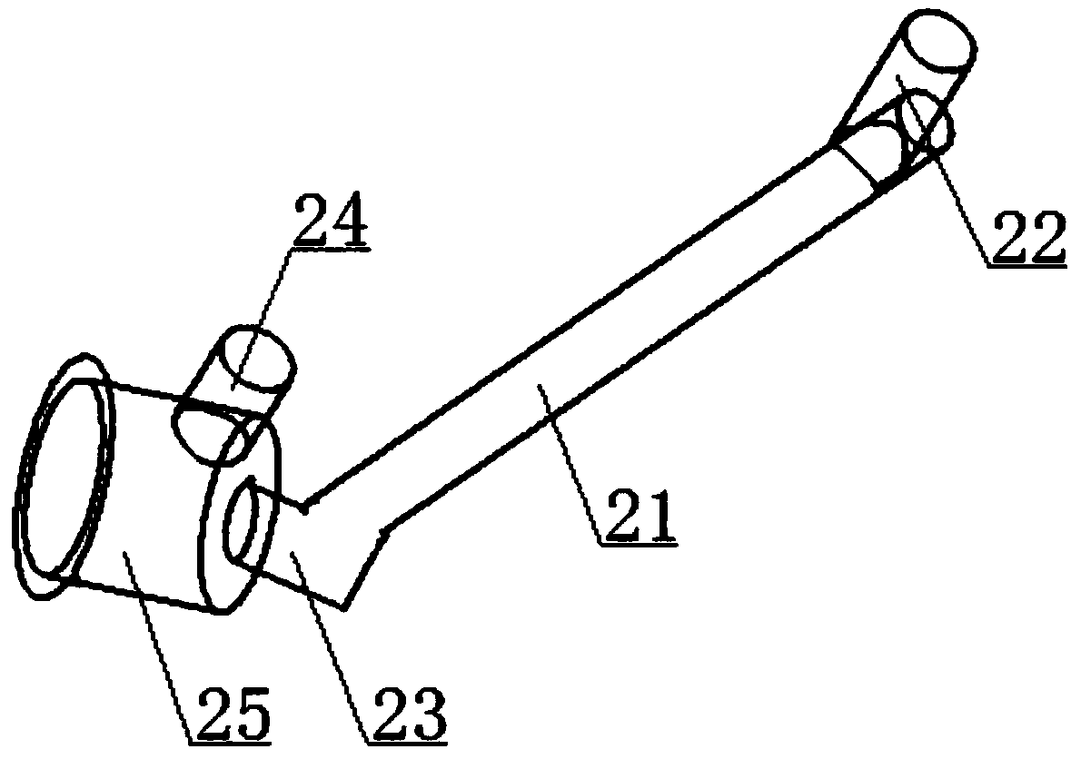
[0021] see Figure 1 to Figure 3 The shown oil circuit layout structure of an engine piston cooling nozzle includes cylinder block oil inlet passage 11 arranged in the cylinder body, intake side transverse main oil passage 12, cylinder head oil inlet passage 14, exhaust side transverse main oil passage The oil passage 17 is characterized in that: it also includes a front end oil passage arranged in the front cover and a solenoid valve mounting hole 25 arranged on the front end oil passage; the oil inlet passage 11 of the cylinder block and the oil inlet passage 14 of the cylinder head are all vertical Arranged directly on the air intake side of the cylinder body, the upper end of the oil inlet passage 11 of the cylinder body is connected with the transverse main oil passage 12 of the intake side, and the lower end of the oil inlet passage 14 of the cy...


PUM


Abstract

The invention relates to an oil way arranging structure of an engine piston cooling nozzle. The oil way arranging structure of the engine piston cooling nozzle comprises a cylinder body oil inlet channel, an air inlet side transverse main oil channel, a cylinder cover oil inlet channel and an exhaust side transverse main oil channel which are all arranged in a cylinder body. The oil way arrangingstructure is characterized in that the oil way arranging structure further comprises a front end oil channel arranged in a front cover and an electromagnetic valve mounting hole formed in the front end oil channel; the upper end of the cylinder body oil inlet channel is connected with the air inlet side transverse main oil channel, and the lower end of the cylinder cover oil inlet channel is connected with the front end part of the air inlet side transverse main oil channel; the cylinder cover oil inlet channel and the font end of the exhaust side transverse main oil channel communicate through the front end oil channel; and a plurality of branch oil ducts are arranged on the exhaust side transverse main oil channel, and each branch oil duct is connected with a piston cooling nozzle assembly. The cylinder body structure can be simplified, the cylinder body casting and machining process is simplified, the production efficiency and the qualified rate of cylinder bodies can be effectivelyimproved, and the cost is lowered; and while production efficiency and the qualified rate of the cylinder bodies are guaranteed, the production efficiency and the machining process of the front covercan be guaranteed.

Description

technical field [0001] The invention relates to an automobile engine, in particular to an oil passage arrangement structure of an engine piston cooling nozzle. Background technique [0002] The automobile engine block is the core component of the engine and the "matrix" of the entire engine assembly. The upper part of the cylinder block cooperates with the cylinder head to form a combustion chamber, and the lower part forms a cavity to provide a movement space for the crank connecting rod mechanism. The cylinder body is generally cast and processed with oil passages to lubricate all parts that need to be lubricated. With the wide application of new technologies such as turbocharging, in-cylinder direct injection, and high compression ratio, the degree of strengthening of the engine is getting higher and higher, and the heat load on the piston is also increasing; in order to reduce the fuel consumption of the engine, reduce the piston To ensure the reliability of piston ope...

Claims


Application Information

Patent Timeline
Patent Type & Authority Applications(China)
IPC IPC(8): F01P3/08F01P7/14
CPCF01P3/08F01P7/14F01P2007/146
Inventor 程涛张晓宇王岳宇苏学颖
Owner CHONGQING CHANGAN AUTOMOBILE CO LTD
Why Eureka
Try Eureka