
Wiring sheet and coil framework provided with wiring sheet

A technology of coil bobbins and lugs, which is applied in the direction of coils, electrical components, circuits, etc., can solve the problems of suction noise movement stagnation, coil burnout, contact burnout, etc., to improve torque bearing capacity and lower bending process requirements , the effect of increasing the contact area

Pending Publication Date: 2018-04-20
DELIXI ELECTRIC
View PDF0 Cites 0 Cited by
  • Summary
  • Abstract
  • Description
  • Claims
  • Application Information

AI Technical Summary

Problems solved by technology

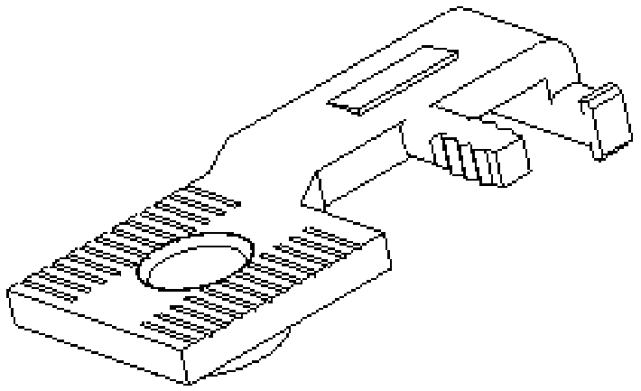
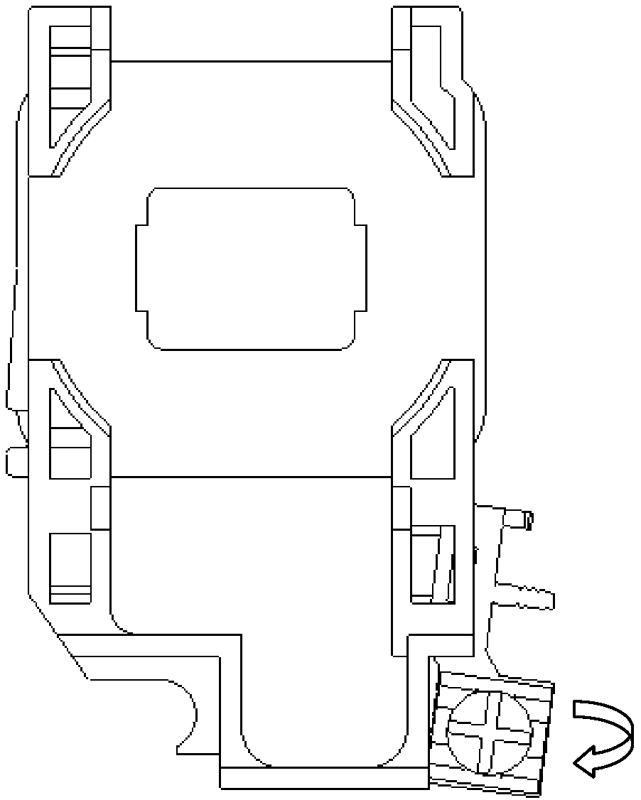
[0004] 1. The fixing method of the lug and the coil frame is unreliable. The lug is only limited by a convex hull and a small area of ​​the coil bobbin, which cannot bear the torque in the screw tightening direction. ,like image 3 As shown in the figure, the arrow in the figure indicates the screw tightening direction, and the enameled wire will be pulled when the lug is unscrewed, which will seriously cause the enameled wire to break; severe enough to affect the use of the product
[0005] 2. The lug and the coil frame are interference fit, and the convex hull on the lug should not be too high, and due to technological problems, the boss of the convex hull cannot make obvious steps, and it is impossible to ensure that the boss and the positioning hole of the bobbin are effectively fixed. ; Unreliable fixation, falling out of the fixing groove, causing the enameled wire to break, and the contactor cannot be closed
This will lead to suction noise or movement stagnation, which will cause serious failures such as coil burnout or contact burnout

Method used


Image

  • Wiring sheet and coil framework provided with wiring sheet
  • Wiring sheet and coil framework provided with wiring sheet
  • Wiring sheet and coil framework provided with wiring sheet

Examples


Embodiment 1

[0032] Such as Figure 4 As shown, a lug includes a positioning part 11 and a fastening part 12, the positioning part 11 is used to connect with the bobbin, the fastening part 12 is provided with a threaded through hole 121, and the threaded through hole 121 is used to connect the locking mechanism For example, screws, anti-slip lines 122 are provided on both sides of the threaded through hole 121; one side of the positioning part 11 has a bend 111, and the bend is used for sliding connection with the chute on the coil frame. Barbs 112 are provided on the contact surface between the bend 111 and the bobbin.

Embodiment 2

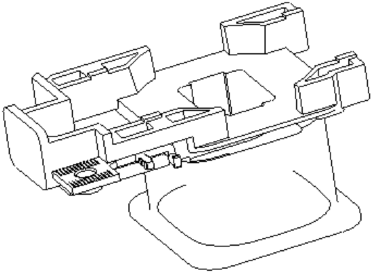
[0034] Such as Figure 5 As shown, a coil bobbin of a lug includes a support frame 21 and a winding reel 22, the support frame 21 has a square chute 211, and the contact surface between the bend 111 of the lug and the coil bobbin has a barb 112, The barb 112 is in interference fit with the chute 211 , and when the lug slides toward the support frame 21 , the interference value between the barb 112 and the chute 211 increases gradually, preventing the lug from loosening after assembly and the winding coming out.

[0035] In this embodiment, the lug and the coil frame do not need to be limited by bosses. A bending surface is added to the side of the lug, and a deep groove is added in the coil bobbin. Through the large-area limit, the screwdriver can withstand the force of the lug in the direction of tightening the screw. Torque, the plastic block does not fall off during the assembly process, thus avoiding the noise of the iron core caused by the plastic block falling to the sur...


PUM


Abstract

The invention relates to a wiring sheet. The wiring sheet comprises a locating part (11) and a fastening part (12), the locating part (11) is used for being connected with a coil framework, and the fastening part (12) is used for being connected with a locking mechanism; the wiring sheet is characterized in that a bending unit (111) is arranged at one side of the locating part (11) and is used forbeing slidably connected with a slide groove in the coil framework. Compared with the prior art, the bending unit is arranged at one side of the locating part of the wiring sheet and is used for being slidably connected with the slide groove in the coil framework, the bending technological requirement is low, by increasing the bending height, the contact area can be increased, thus the torque bearing capacity of the wiring sheet is improved, when a screwdriver screws on a screw, displacement is not easily generated, it is avoided that when an enameled wire is damaged and broken, a product isinvalid since the tail of the wiring sheet is screwed off, and a plastic block is prevented from shedding when the coil framework is broken.

Description

technical field [0001] The invention relates to an electromagnetic coil frame, in particular to a connecting piece and a coil frame with the connecting piece. Background technique [0002] The electromagnetic coil is usually wound on the coil frame, and the coil frame includes a support frame and a winding disk, and one side of the support frame is connected with a lug. [0003] The current common lug structure is as follows: figure 1 As shown, the fixing method of the lug and the coil frame is as follows figure 2 As shown in the figure, after the interference fit between the lug and the coil frame, the lug is clamped and fixed by the boss and the positioning hole. But this structure obviously has the following defects: [0004] 1. The fixing method of the lug and the coil frame is unreliable. The lug is only limited by a convex hull and a small area of ​​the coil bobbin, which cannot bear the torque in the screw tightening direction. ,Such as image 3 As shown in the ...

Claims


Application Information

Patent Timeline
IPC IPC(8): H01F5/04H01F5/02
CPCH01F5/02H01F5/04
Inventor 李晓庆金鹏郑天云李新叶
Owner DELIXI ELECTRIC
Learn More