Electronic SMT assembly

A patch and component technology, applied in electrical components, transformer/inductor components, circuits, etc., can solve the problems of large PCB board area, solder joints, affecting the patch effect, etc., to improve product reliability, Avoid virtual welding of solder joints and enhance the effect of patch effect

Pending Publication Date: 2018-04-20
GUANGZHOU ZHIYUAN ELECTRONICS CO LTD
View PDF6 Cites 0 Cited by
  • Summary
  • Abstract
  • Description
  • Claims
  • Application Information

AI Technical Summary

Problems solved by technology

[0003] However, the frame of the above-mentioned transformer is a single-cavity structure, there is no lower cavity to avoid the components, and a laminated structure cannot be formed, which occupies a large PCB area. There is no isolation between components, the reliability of the product is not high enough, and the flatness of the pins cannot be guaranteed when the varnish is removed by dipping tin, which affects the placement effect, and may lead to solder joints after reflow.

Method used


Image

  • Electronic SMT assembly
  • Electronic SMT assembly

Examples


Embodiment Construction
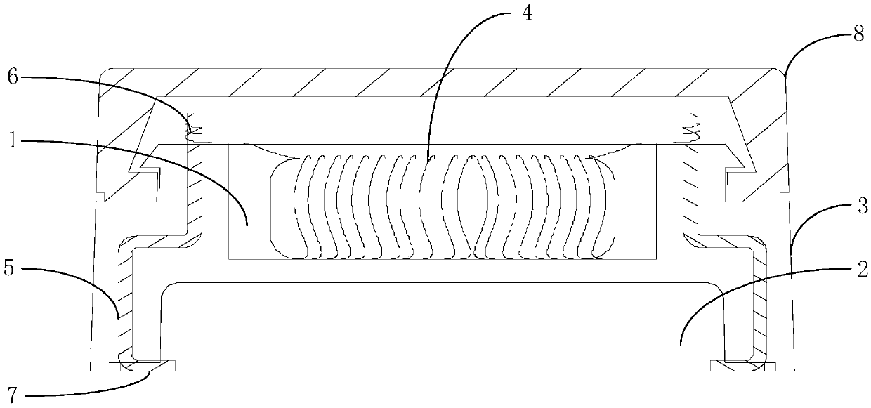
[0017] The core idea of ​​the present invention is to provide an electronic patch assembly, which can reduce the area occupied by the PCB board, and realize effective isolation between the magnetic coil and components, improve product reliability, enhance the effect of patching, and avoid soldering after reflow. Weld problem.

[0018] The following will clearly and completely describe the technical solutions in the embodiments of the present invention with reference to the accompanying drawings in the embodiments of the present invention. Obviously, the described embodiments are only some, not all, embodiments of the present invention. Based on the embodiments of the present invention, all other embodiments obtained by persons of ordinary skill in the art without making creative efforts belong to the protection scope of the present invention.

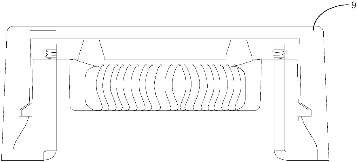
[0019] The first electronic patch component provided by the embodiment of this application is as figure 1 as shown, figure 1 A schem...


PUM


Abstract

The invention discloses an electronic SMT assembly. The assembly includes an insulated base with an upper cavity and a lower cavity, the upper cavity is insulated and separated from the lower cavity,a magnetic coil is contained in the upper cavity, pins penetrating through the peripheral part of the upper cavity and the peripheral part of the lower cavity are embedded in the insulated base, reeling ends used for reeling the magnetic coil are arranged at the upper portions of the pins, and the lower portions of the pins are provided with SMT ends used for being connected to a PCB. The electronic SMT assembly can reduce the occupied area of the PCB, achieve effective insulation between the magnetic coil and a component, improve the reliability of a product, enhance the SMT effect and avoidthe cold joint problem of welding points after backflow.

Description

technical field [0001] The invention belongs to the technical field of electronic equipment, in particular to an electronic patch component. Background technique [0002] The structure of the existing electronic patch components, taking the transformer skeleton and the current transformer as an example, mainly has a plastic shell, the plastic shell is integrally formed by insulating materials and metal pins, the metal pins are arranged on both sides of the plastic shell, and the pins The quantity depends on the design. The bottom of the pin is made of seagull feet, which is beneficial to the reflow soldering of the placement machine and realizes automatic production; the top or bottom of the pin is assembled with the magnetic coil. First, the magnetic coil that has been wound with enameled wire is put into In the cavity of the plastic shell, the magnetic coil wire ends are wound on the corresponding winding pin terminals of the plastic shell, and then the wrapped wire pin te...

Claims


Application Information

Patent Timeline
Patent Type & Authority Applications(China)
IPC IPC(8): H01F27/30H01F27/29
CPCH01F27/292H01F27/306
Inventor 周立功邓涛韦敏忠
Owner GUANGZHOU ZHIYUAN ELECTRONICS CO LTD
Why Eureka
Try Eureka