Power distribution cabinet with heat-radiation waterproof cabinet door

A technology for waterproof cabinet doors and power distribution cabinets, applied in the electric power field, can solve the problems of poor waterproof performance of power distribution cabinets, poor heat dissipation effect, limited number of heat dissipation holes, etc., so as to improve work stability and improve heat dissipation effect. , the effect of reducing vibration

Inactive Publication Date: 2018-04-20
黄月连
View PDF0 Cites 5 Cited by
  • Summary
  • Abstract
  • Description
  • Claims
  • Application Information

AI Technical Summary

Problems solved by technology

[0002] In the existing power system, the power distribution cabinet is the final equipment of the power system, and the power equipment in the power distribution cabinet also generates a lot of heat. The cooling holes of the existing outdoor power distribution cabinet are generally set at the bottom of the cabinet. , the heat dissipation holes at the bottom will not allow rainwater to enter, and have a good waterproof effect, but the number of heat dissipation holes set at the bottom is limited, so the heat dissipation effect is not very good; and in the hot summer, the heat dissipation holes of the power distribution cabinet are still Because there is no wind blowing in, the heat inside the power distribution cabinet will not condense, and the temperature will become higher and higher, resulting in damage to electrical equipment, and the waterproof performance of the existing power distribution cabinet is not very good; therefore, we need a A kind of power distribution cabinet with heat dissipation and waterproof cabinet door

Method used


Image

  • Power distribution cabinet with heat-radiation waterproof cabinet door
  • Power distribution cabinet with heat-radiation waterproof cabinet door
  • Power distribution cabinet with heat-radiation waterproof cabinet door

Examples


Embodiment Construction

[0015] The technical solution of this patent will be further described in detail below in conjunction with specific embodiments.

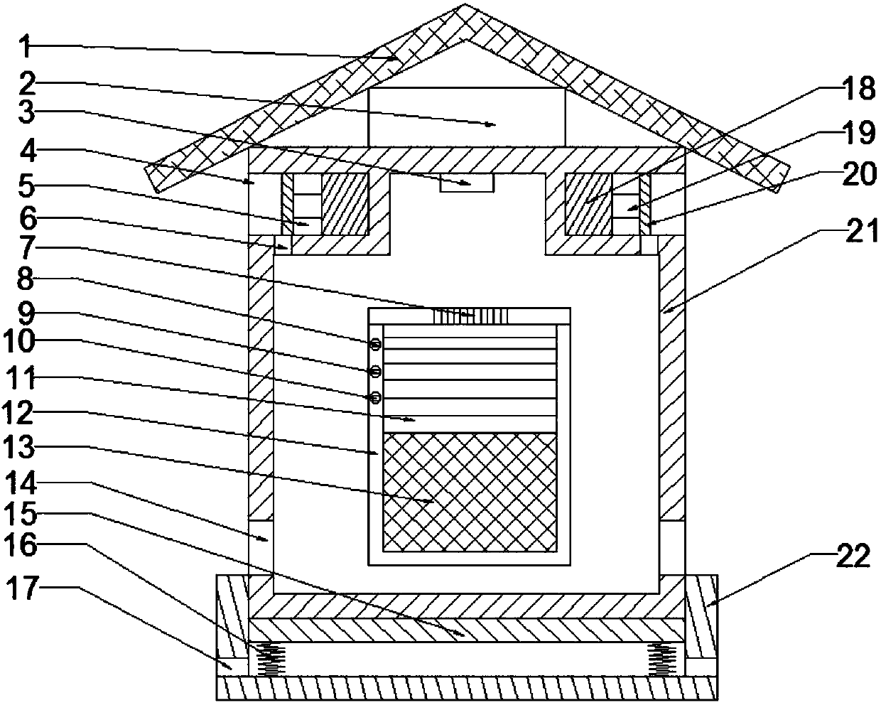
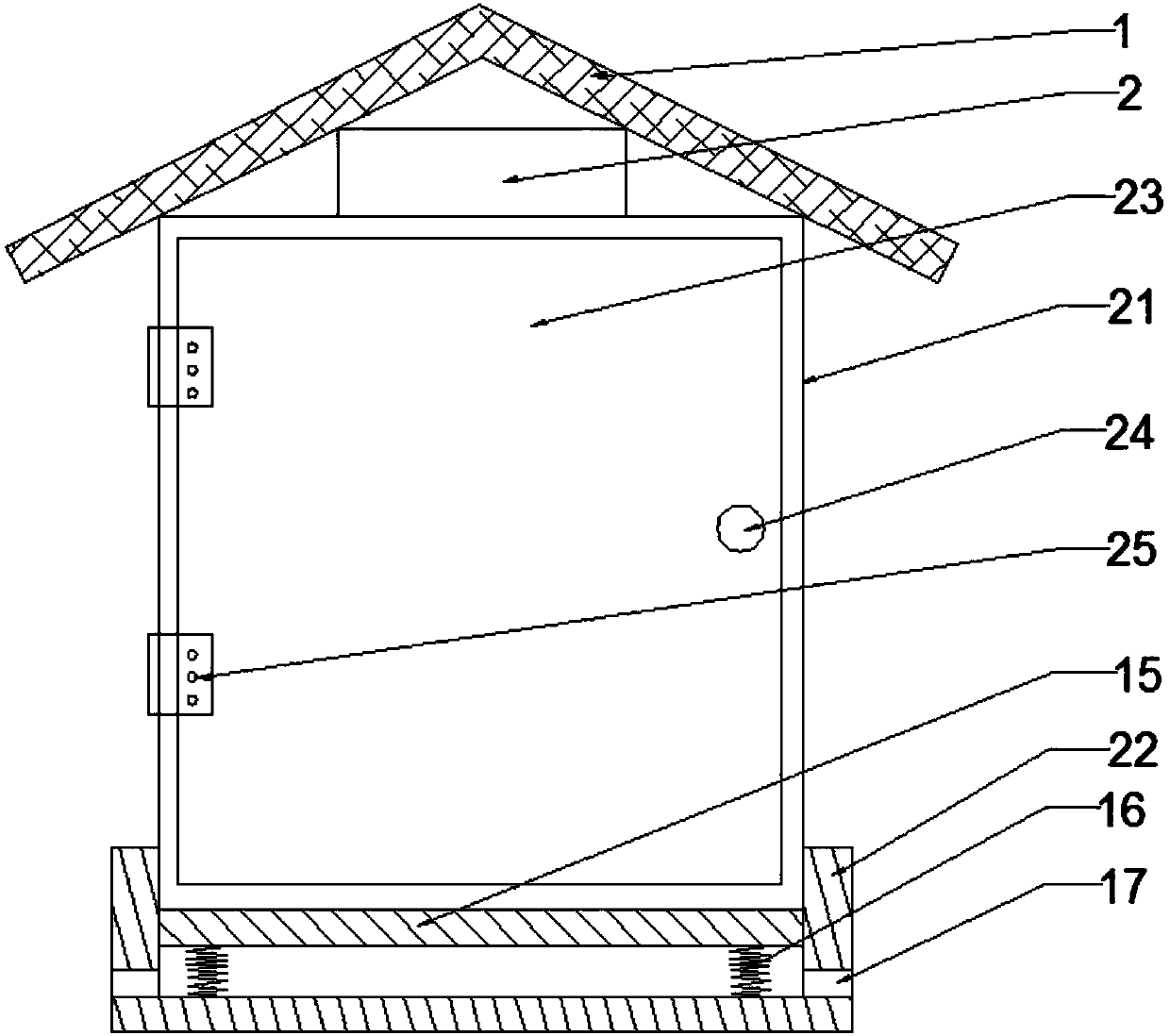
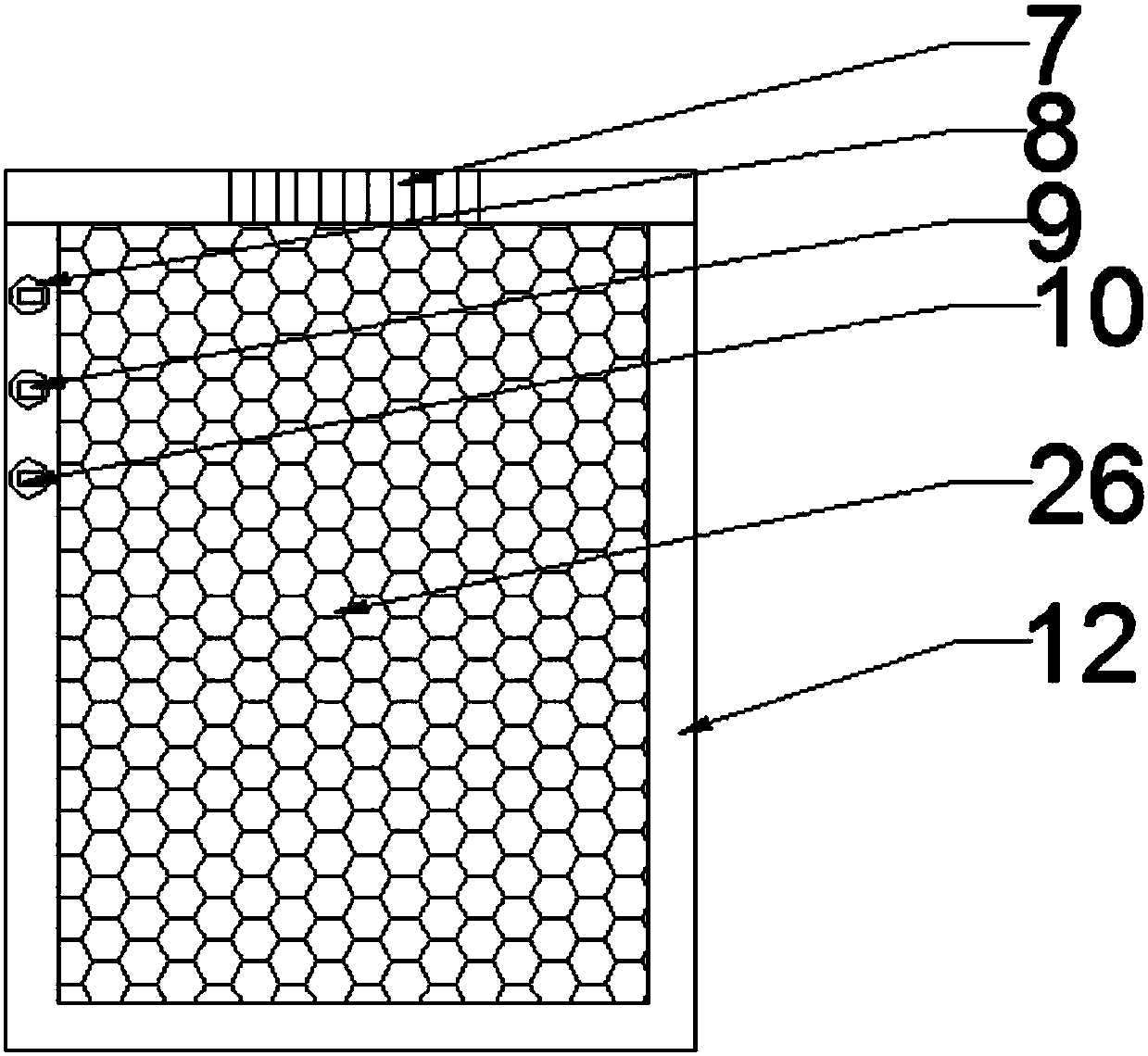
[0016] see Figure 1-3 , a power distribution cabinet with a heat-dissipating and waterproof cabinet door, including a base device and a power distribution cabinet device; Through hole 6, bidirectional rotating motor 7, controller 8, temperature sensor 9, humidity sensor 10, sealed rolling door 11, distribution box 12, protective net 13, air inlet hole 14, cylinder 18, telescopic rod 19, piston 20, cabinet Body 21, cabinet door 23, cabinet door lock 24, hinge 25 and dustproof ventilation net 26; the front side of the cabinet body 21 is provided with cabinet door 23 through hinge 25, and cabinet door 23 is provided with cabinet door lock 24; The above-mentioned distribution box 12 is fixedly arranged in the inner cavity of the cabinet body 21, and the front side of the distribution box 12 is provided with a sealed rolling door 11, and the sealed ro...


PUM


Abstract

The invention discloses a power distribution cabinet with a heat dissipation and waterproof cabinet door, comprising a base device and a power distribution cabinet device; the front side of the cabinet body is provided with a cabinet door through hinges, and the cabinet door is provided with a cabinet door lock; the The sealed rolling shutter door is arranged vertically, and the sealed rolling shutter door body is made of transparent material; the base is set on the lower side of the cabinet body, the base is in the shape of a groove with an upward opening, and the opening section is the same as the cross section of the cabinet body. A number of drainage holes are evenly arranged on the side surface; the power distribution cabinet with the heat dissipation and waterproof cabinet door of the present invention can automatically dissipate heat and waterproof, can improve the air flow in the power distribution cabinet, further improve the heat dissipation effect, and improve the setting of the shock absorption base. The working stability of the power distribution cabinet is improved, the displacement of the power distribution cabinet is avoided, and the vibration can be effectively reduced. In addition, solar power generation is used to supply power to the power distribution cabinet, which saves energy and reduces the cost of use.

Description

technical field [0001] The invention relates to the field of electric power, in particular to a power distribution cabinet with a heat-dissipating and waterproof cabinet door. Background technique [0002] In the existing power system, the power distribution cabinet is the final equipment of the power system, and the power equipment in the power distribution cabinet also generates a lot of heat. The cooling holes of the existing outdoor power distribution cabinet are generally set at the bottom of the cabinet. , the heat dissipation holes at the bottom will not allow rainwater to enter, and have a good waterproof effect, but the number of heat dissipation holes set at the bottom is limited, so the heat dissipation effect is not very good; and in the hot summer, the heat dissipation holes of the power distribution cabinet are still Because there is no wind blowing in, the heat inside the power distribution cabinet will not condense, and the temperature will become higher and ...

Claims


Application Information

Patent Timeline
Patent Type & Authority Applications(China)
IPC IPC(8): H02B1/56H02B1/54H02B1/28H02B1/30
CPCH02B1/56H02B1/28H02B1/30H02B1/54
Inventor 黄月连
Owner 黄月连
Why Eureka
Try Eureka