Switching circuit control circuit and switching circuit

A switching circuit and control circuit technology, applied in electrical components, output power conversion devices, AC power input into DC power output and other directions, can solve the problems of long startup time, short conduction time, slow rise of output voltage VO, etc. , to achieve the effect of enhancing the charging capacity, fast startup, and prolonging the conduction time

Pending Publication Date: 2018-04-20
JOULWATT TECH INC LTD
View PDF0 Cites 2 Cited by
  • Summary
  • Abstract
  • Description
  • Claims
  • Application Information

AI Technical Summary

Problems solved by technology

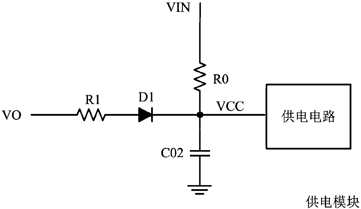
[0004] However, in actual work, in order to filter out the power frequency ripple, the compensation capacitor in the compensation circuit and the output capacitor in the switch circuit are often selected very large, resulting in the output voltage VO rising very slowly after the drive circuit is started, and each The conduction time of the switching cycle is very short, so the output voltage VO in the power supply module has a weak ability to effectively charge the capacitor C02. It takes a long time from the start of the drive circuit to the power supply voltage VCC to reach the balance of power supply, and it often needs to be restarted several times. Complete the start-up process, which makes the start-up time very long, and even the start-up process cannot be completed in the case of continuous power-on and off.

Method used


Image

  • Switching circuit control circuit and switching circuit
  • Switching circuit control circuit and switching circuit
  • Switching circuit control circuit and switching circuit

Examples


Embodiment Construction

[0027] Preferred embodiments of the present invention will be described in detail below with reference to the accompanying drawings, but the present invention is not limited to these embodiments. The present invention covers any alternatives, modifications, equivalent methods and schemes made within the spirit and scope of the present invention.

[0028] In order to provide the public with a thorough understanding of the present invention, specific details are set forth in the following preferred embodiments of the present invention, but those skilled in the art can fully understand the present invention without the description of these details.

[0029] In the following paragraphs the invention is described more specifically by way of example with reference to the accompanying drawings. It should be noted that all the drawings are in simplified form and use inaccurate scales, which are only used to facilitate and clearly assist the purpose of illustrating the embodiments of t...


PUM


Abstract

The invention discloses a switching circuit control circuit and a switching circuit. The switching circuit control circuit comprises a compensation circuit which comprises an output voltage judging circuit, a timing circuit, a transconductance gain adjusting circuit and a transconductance amplifier, wherein the first input end of the transconductance amplifier receives a first voltage signal representing the output current, and the second input end of the transconductance amplifier receives a reference voltage, the output end of the transconductance amplifier is connected with one end of a compensation capacitor, and the other end of the compensation capacitor is grounded, the output voltage judging circuit and the timing circuit are used for receiving a sampling signal representing the output voltage and are respectively connected to the transconductance gain adjusting circuit, the transconductance gain adjusting circuit controls the transconductance gain of the transconductance amplifier, the charging current of the compensation capacitor is increased in the starting stage of the switching circuit, and the voltage rise of the compensation capacitor is accelerated. According to the invention, the rising rate of the voltage during the initial working state of the compensation capacitor is controlled, so that the compensation capacitor can be rapidly charged, and then rapid starting is completed.

Description

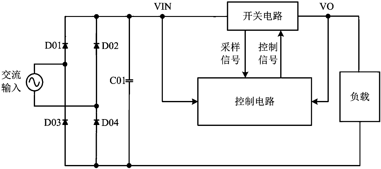
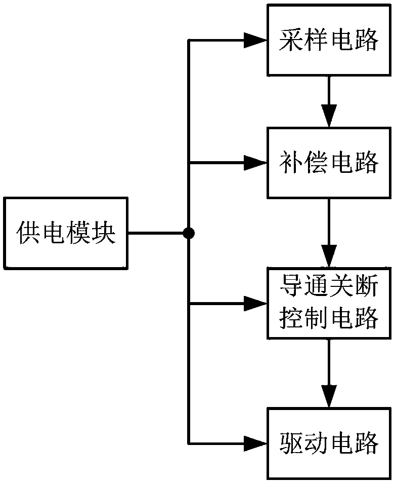
technical field [0001] The invention relates to the field of switch circuits, and more specifically, to a switch circuit control circuit and a switch circuit. Background technique [0002] The block diagram of the traditional LED drive circuit is as follows: figure 1 As shown, the external AC input voltage is rectified by the rectifier bridge to obtain a pulsating DC voltage VIN, and then the DC voltage VIN is converted and processed by the switching circuit to generate an output voltage VO to supply the load. The control circuit receives the DC voltage VIN, the output voltage VO and the output of the switching circuit The sampling signal is used to generate a control signal for controlling the switch state in the switch circuit, so that the switch circuit outputs an expected output voltage signal. [0003] Such as figure 2 As shown, the control circuit generally includes five sub-modules: power supply module, sampling circuit, compensation circuit, on-off control circuit...

Claims


Application Information

Patent Timeline
Patent Type & Authority Applications(China)
IPC IPC(8): H02M1/36H02M7/219
CPCH02M1/36H02M7/219
Inventor 胡长伟黄必亮周逊伟
Owner JOULWATT TECH INC LTD
Why Eureka
Try Eureka