
Uniform heating plate cooling device with support post structure and fabrication method of cooling device

A technology of heat dissipation device and vapor chamber, which is applied to structural parts of electrical equipment, modification by conduction heat transfer, cooling/ventilation/heating transformation, etc. Increase in size, capillary limit, low condensation limit, etc., to achieve the effect of improving capillary limit and thermal conductivity, improving heat dissipation performance, and improving heat exchange efficiency

Inactive Publication Date: 2018-04-20
716TH RES INST OF CHINA SHIPBUILDING INDAL CORP
View PDF8 Cites 28 Cited by
  • Summary
  • Abstract
  • Description
  • Claims
  • Application Information

AI Technical Summary

Problems solved by technology

[0006] However, in the existing vapor chamber heat dissipation device for electronic equipment, the liquid working medium only relies on the sintering of the inner surface of the working chamber and the return flow of the liquid-absorbing core with a capillary structure such as a wire mesh. The capillary limit and condensation limit of the heat transfer process are relatively low, and the thermal conductivity It is difficult to further improve the structural size; when the vapor chamber heat sink is in contact with the electronic device, the vapor chamber heat sink can only be placed horizontally. The force is small and the return flow of the liquid working medium is slow, which cannot achieve the expected heat dissipation effect, which brings great limitations to the application of the vapor chamber cooling device.
[0007] It can be seen that although the design and manufacturing technology of vapor chamber heat sinks are constantly improving, the existing vapor chamber heat sinks still have defects such as a single return path of liquid working fluid and limited layout methods, which urgently need to be further improved

Method used


Image

  • Uniform heating plate cooling device with support post structure and fabrication method of cooling device
  • Uniform heating plate cooling device with support post structure and fabrication method of cooling device
  • Uniform heating plate cooling device with support post structure and fabrication method of cooling device

Examples


Embodiment

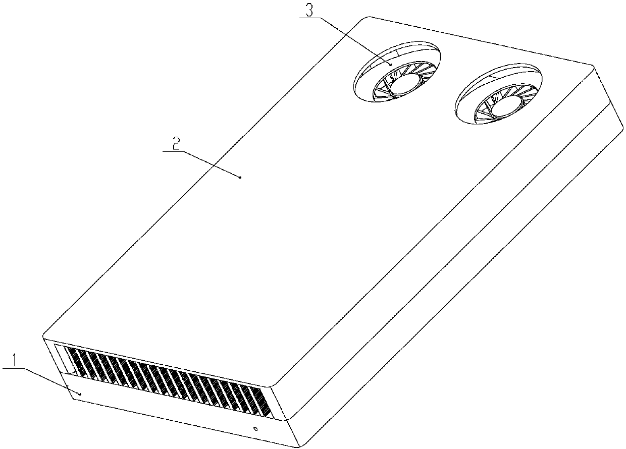
[0065] A vapor chamber cooling device with a support column structure, comprising a vapor chamber radiator 1 with a support column structure, a windshield 2 and a vortex fan 3, such as figure 1 shown;

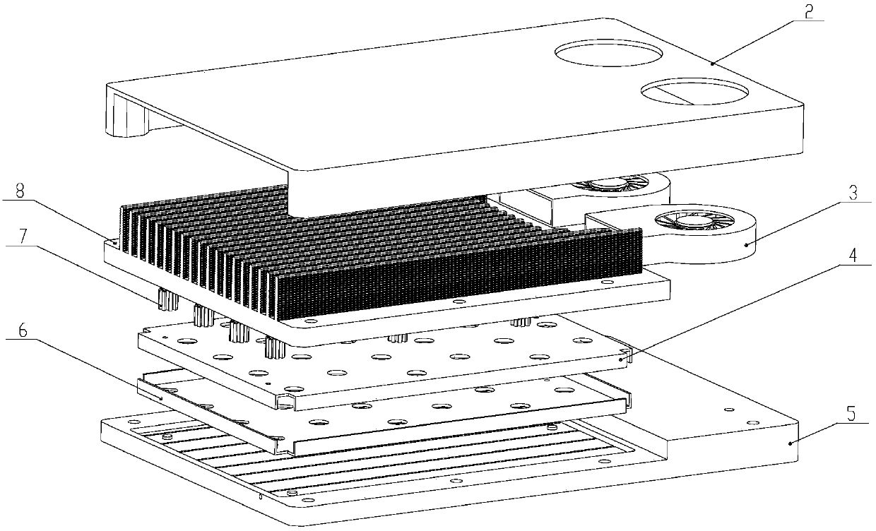
[0066] Such as figure 2 As shown, the vapor chamber radiator 1 is composed of an upper cover plate 8, a lower cover plate 5, a composite reflow structure, a support column 7 and a nano-liquid working medium, and the upper cover plate 8 and the lower cover plate 5 are welded to form a vapor chamber working chamber , the support column 7 is welded to the inner surface of the chamber of the vapor chamber to enhance the strength of the vapor chamber shell and eliminate the influence of the steam pressure of the internal working medium on the shell; the composite reflow structure consists of the upper cover groove 9, the second The wire mesh capillary liquid-absorbing core 4, the lower cover plate groove 12, the second wire mesh capillary liquid-absorbing core 6 and the support co...


PUM


Abstract

The invention relates to a uniform heating plate cooling device with a support post structure and a fabrication method of the cooling device. The cooling device comprises a wind shielding plate, eddyfans and a uniform heating plate heat sink, wherein the uniform heating plate heat sink comprises a working cavity, a composite backflow structure, capillary structure support posts and a nanometer liquid-state working medium, the working cavity is formed by welding an upper cover plate and a lower cover plate, the upper cover plate is provided with rippled-shaped cooling fins, the lower cover plate is provided with heat conduction bosses, the composite backflow structure comprises upper cover plate grooves, a first silk-screen capillary liquid absorption core, lower cover plate grooves, a second silk-screen capillary liquid absorption core and support posts, the support posts are provided with capillary structures, and a plurality of through holes are formed in the first silk-screen capillary liquid absorption core and the second first silk-screen capillary liquid absorption core and are used for the support posts to penetrate through. By the support posts with the capillary structures, the backflow speed of the liquid-state working medium in the working cavity of the uniform heating plate and the heat transfer efficiency are improved, the structure strength is improved, the cooling device is applicable to an occasion where a single heat source and multiple heat sources are horizontally or vertically arranged, the application range of the uniform heat plate heat sink is expanded, and the cooling device has the characteristics of compact volume, high safety, high environmental adaptability and the like.

Description

technical field [0001] The invention relates to the heat dissipation technology of electronic equipment, in particular to a vapor chamber heat dissipation device with a support column structure and a preparation method thereof. Background technique [0002] With the continuous development of microelectronics technology and large-scale integrated circuit technology, while the performance of electronic equipment continues to improve, the power of internal components and unit volume density also continue to increase. The miniaturization of equipment makes heat dissipation design more difficult, and heat dissipation problems have It has become a bottleneck that affects the further development of high-performance and miniaturized electronic equipment. The thermal design technology aimed at effectively controlling the temperature rise of internal components has become one of the key technologies of electronic equipment. [0003] In the existing heat dissipation technology of elect...

Claims


Application Information

Patent Timeline
IPC IPC(8): H05K7/20B23P15/26
CPCB23P15/26H05K7/20136H05K7/20327H05K7/20336H05K7/20509
Inventor 卢锡铭翟永宁杨乾乾朱勇孙成宽张苗夏川张梅
Owner 716TH RES INST OF CHINA SHIPBUILDING INDAL CORP
Features
  • Generate Ideas
  • Intellectual Property
  • Life Sciences
  • Materials
  • Tech Scout
  • Unparalleled Data Quality
  • Higher Quality Content
  • 60% Fewer Hallucinations
Learn More