Elastic wiring member

A wiring component, elastic technology, applied in the direction of printed circuit components, elastic polymer dielectrics, circuit bendable/stretchable components, etc., can solve the problems of not being able to elongate, etc., and achieve inhibition of peeling and connection The effect of excellent stability

Inactive Publication Date: 2018-04-20
SEKISUI POLYMATECH CO LTD
View PDF7 Cites 3 Cited by
  • Summary
  • Abstract
  • Description
  • Claims
  • Application Information

AI Technical Summary

Problems solved by technology

However, although this flexible substrate can be bent, it cannot be stretched when pulled, so it is not a stretchable part.

Method used


Image

  • Elastic wiring member
  • Elastic wiring member
  • Elastic wiring member

Examples


no. 1 example

[0070] First embodiment: Figure 1 ~ Figure 4

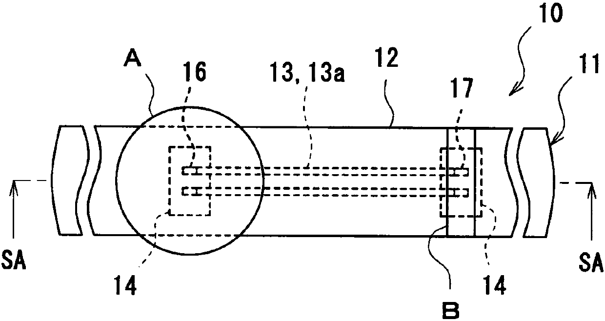
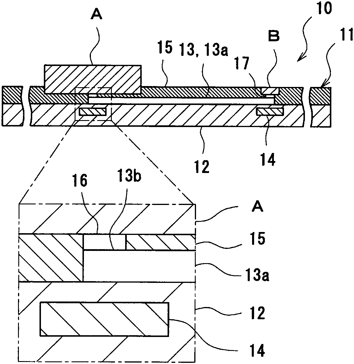
[0071] exist Figure 1 ~ Figure 4 The elastic wiring member 11 of the first embodiment is shown in . figure 1 In order to schematically show a plan view of the electronic device 10, the electronic device 10 includes an electronic device main body A as a "connection object part" among the above-mentioned elastic wiring members 11, and an electronic component B as a "connection object part". figure 2 for its cross-sectional view. Here, the electronic device body A can be applied to a watch body such as a digital watch, and the electronic component B can be applied to an LED for lighting, for example, but the "connection object part" is not limited thereto.

[0072] Such as figure 1 or figure 2 As shown, in the electronic device 10 , the elastic wiring member 11 is connected to the main body A of the electronic device through the contact 16 , and is connected to the electronic component B through the contact 17 . The elastic...

no. 2 example

[0100] Second embodiment: Figure 6 ~ Figure 8

[0101] Now, the elastic wiring member 21 of the second embodiment will be described. Image 6 shown with Figure 4 A schematic plan view of the corresponding elastic wiring member 21, Figure 7 show Image 6 cross-sectional view. also, Figure 8 is a cross-sectional view when the substrate 12 is divided into two in the short-side direction. In these figures, the electronic components connected to the elastic wiring member 21 and the cover member 15 are omitted.

[0102] Compared with the elastic wiring member 11 of the first embodiment, the elastic wiring member 21 is different in the position and shape of the reinforcing member 24 . Such as Image 6 As shown, when viewed from the surface of the base sheet 12 (in a plan view), the reinforcing member 24 of the elastic wiring member 21 is provided at least three side positions surrounding the outer edge of the connecting portion 13b of the elastic wiring 13 (U glyphs), an...

no. 3 example

[0104] Third embodiment: Figure 9 , Figure 10

[0105] shows the elastic wiring member 31 of the third embodiment Figure 9 , is an enlarged plan view near contact 16, Figure 10 is its cross-sectional view. In addition, in Figure 9 or Figure 10 In both, the electronic components to be connected and the cover member 15 are omitted.

[0106] The elastic wiring member 31 of this embodiment also differs in the shape of the reinforcing member 34 from the elastic wiring members 11 and 21 of the other embodiments. Such as Figure 9 As shown, the reinforcing member 34 is also formed in a U-shape when viewed from above, so although it looks similar to the shape of the elastic wiring 24 at first glance, the elastic wiring 24 is formed by standing three planar reinforcing members in a U shape. The stretchable wiring 34 in this embodiment is different in that the planar reinforcing member is punched into a U-shape and then laminated on the surface of the base sheet 12 .

[0...


PUM

PropertyMeasurementUnit
electrical resistivityaaaaaaaaaa
hardnessaaaaaaaaaa

Abstract

An elastic member which is used for the connection of an electronic component and an external electronic device, and which is not susceptible to change in the resistance even if stretched. An elasticwiring member 11 which is composed of: a stretchable wiring line 13 that connects a contact 16 of an electronic device main body A and a contact 17 of an electronic component with each other; and a base sheet 12 that holds the stretchable wiring line 13 and is composed of a rubber-like elastic body. The base sheet 12 is provided with a reinforcing member 14 at a position adjacent to a connection part 13b of the stretchable wiring line 13, which is connected to the contact 16, 17, when viewed from the front surface of the base sheet 12 for the purpose of suppressing stretching of the base sheet12 and preventing deformation of the stretchable wiring line 13 in the connection part 13b.

Description

technical field [0001] The present invention relates to a stretchable elastic wiring member including conductive wiring. Background technique [0002] When installing electronic components on electronic equipment, a bendable flexible substrate with windability is used. However, although such a flexible substrate can be bent, it cannot be stretched when pulled, so it is not a stretchable part. In contrast, JP 2007-173226 A (Patent Document 1) describes an example in which an electronic component is mounted on a stretchable rubber-like elastic body. The technique described in this gazette is to provide a conductive portion in which conductive particles are in contact with each other on a stretchable base material mainly composed of rubber, so that the entire structure is stretchable. [0003] prior art literature [0004] patent documents [0005] Patent Document 1: Japanese Patent Laid-Open No. 2007-173226 Contents of the invention [0006] The problem to be solved by ...

Claims


Application Information

Patent Timeline
Patent Type & Authority Applications(China)
IPC IPC(8): H01B7/10H05K1/02H05K1/03
CPCH05K1/0283H05K3/0014H05K3/284H05K2201/0133H05K2201/0314H05K2201/0323H05K2201/09118H05K2201/2009H05K2203/1316H01B7/10H01B7/02H01B7/04H05K1/0213H05K1/18
Inventor 菊地梢
Owner SEKISUI POLYMATECH CO LTD
Why Eureka
Try Eureka