Gear shaping clamp for flange of transmission

A transmission and fixture technology, applied in the field of clamping devices for workpieces, can solve problems such as poor clamping effect, inconvenient installation and disassembly, and difficulty in providing clamping force.

Inactive Publication Date: 2018-04-24
重庆市乐珐机电有限责任公司
View PDF9 Cites 4 Cited by
  • Summary
  • Abstract
  • Description
  • Claims
  • Application Information

AI Technical Summary

Problems solved by technology

[0004] However, the above-mentioned patent still has the following defects: only using the pressing block to clamp the lower part of the flange, it is difficult to provide a sufficient clamping force, the clamping e

Method used


Image

  • Gear shaping clamp for flange of transmission
  • Gear shaping clamp for flange of transmission

Examples


Embodiment Construction

[0020] The present invention will be described in further detail below by means of specific embodiments:

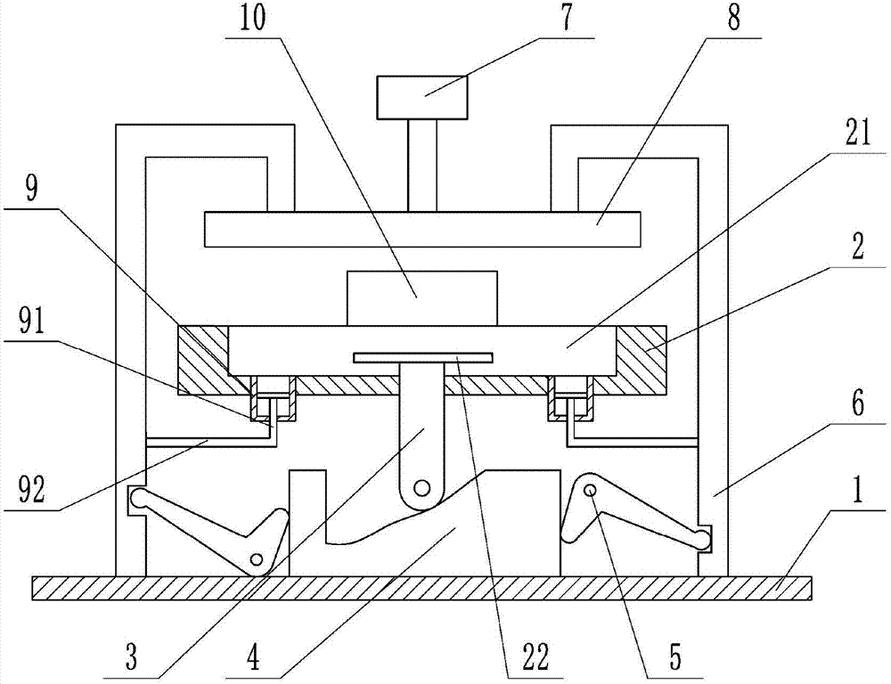
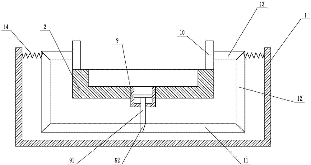
[0021] The reference signs in the drawings of the description include: frame 1, positioning plate 2, positioning notch 21, circular bottom plate 22, support rod 3, cross bar 4, "V"-shaped driving rod 5, push rod 6, cylinder 7 , Annular platen 8, piston cylinder 9, piston rod 91, horizontal rod 92, clamping block 10, first wedge bar 11, second wedge bar 12, third wedge bar 13, spring 14.

[0022] Such as figure 1 As shown, the gear shaper fixture for the transmission flange includes a frame 1, a linkage device and two clamping devices. A positioning disc 2 is welded on the frame 1, and a positioning notch 21 for placing the flange is opened on the positioning disc 2. , the positioning notch 21 is also slidingly connected with a circular bottom plate 22, the center of the circular bottom plate 22 coincides with the center of the positioning notch 21, and the diameter of th...


PUM


Abstract

The invention belongs to the field of workpiece clamping devices, and particularly relates to a gear shaping clamp for a flange of a transmission. The gear shaping clamp comprises a machine frame, a linkage device and a clamping device; a positioning disc is fixedly arranged on the machine frame; a positioning spigot is formed in the positioning disc; the linkage device comprises a supporting rod,a cross rod, V-shaped shifting rods and push rods; a base plate is arranged at the upper end of the supporting rod and is connected in the positioning spigot in a sliding mode; a wedge groove is formed in the cross rod; clamping grooves are formed in the push rods; one ends of the V-shaped shifting rods abut against the cross rod, and the other ends of the V-shaped shifting rods are clamped in the clamping grooves in the push rods; a pressing plate is arranged at the upper ends of the push rods; the clamping device comprises piston cylinders and a clamping block; the piston cylinders are arranged at the bottom of the positioning spigot and communicates with the positioning spigot; wedge surfaces are arranged the piston rods, and the piston rods are fixedly connected to the push rods; andwedge rods are fixedly connected to the clamping block and abut against the piston rods. The gear shaping clamp has the advantages that the purpose of preventing displacement in the machining processof inner teeth of the flange can be achieved, and the gear shaping clamp is mainly used for fixing the flange in the machining process.

Description

technical field [0001] The invention belongs to the field of clamping devices for workpieces, and in particular relates to a gear shaping fixture for a transmission flange. Background technique [0002] During the process of inserting the internal teeth of the flange, due to the large insertion force, the flange will move, which will lead to the phenomenon of disordered teeth. In the process of clamping the flange, there will be a long time for alignment, which will affect the work efficiency. , The processing quality is low, its installation and disassembly is not convenient enough, and the flange plate has many shortcomings such as poor stability during the slotting process. [0003] For this reason, Chinese patent CN204430472U discloses a kind of flange plate gear positioning device, including: a positioning plate, the upper part of the positioning plate is provided with a positioning notch; the flange is placed inside the positioning notch; the middle part of the positio...

Claims


Application Information

Patent Timeline
IPC IPC(8): B23Q3/06
CPCB23F23/06
Inventor 印承霜
Owner 重庆市乐珐机电有限责任公司
Why Eureka
Try Eureka