Piezoelectric wind energy collecting device applied in high-voltage grid

A high-voltage power grid and collection device technology, applied in piezoelectric effect/electrostrictive or magnetostrictive motors, wind power generation, generator/motor, etc., can solve problems such as complex mechanical structure, high cost, and low power generation efficiency , to achieve the effects of high energy harvesting efficiency, extended service life, and large deformation frequency

Active Publication Date: 2018-04-24
SOUTHWEST JIAOTONG UNIV
View PDF2 Cites 6 Cited by
  • Summary
  • Abstract
  • Description
  • Claims
  • Application Information

AI Technical Summary

Problems solved by technology

[0003] According to the search, there have been technologies related to wind energy harvesting devices. For example, "A Piezoelectric Energy Harvesting Method and Device Using Wind Energy" disclosed in Chinese Patent Application No. 201010516391. The repulsion to the fixed magnet on the cantilever beam causes the cantilever beam to vibrate and generate electric energy. The mechanical structure of the device is relatively complicated and the cost is high
Another example is the "wind energy harvester based on flexible polymer piezoelectric material" disclosed in Chinese patent application No. 201610386604.3. The rotation of the blades drives the turntable, and the rotation of the turntable will periodically beat the flexible piezoelectric polymer cantilever beam. The piezoelectric film is knocking and recovering. Electric energy is generated in the vibration of the deformation, the deformation of the flexible piezoelectric material of the device cannot be maximized, the power generation efficiency is low, and the scope of application of this type of device is small, and it is only suitable for wind energy harvesting where the wind direction is directly in front of the blade , the value of promotion and application is low

Method used


Image

  • Piezoelectric wind energy collecting device applied in high-voltage grid
  • Piezoelectric wind energy collecting device applied in high-voltage grid
  • Piezoelectric wind energy collecting device applied in high-voltage grid

Examples


Embodiment Construction

[0017] The present invention will be further described in detail below in conjunction with the accompanying drawings and specific embodiments.

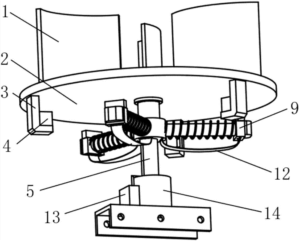
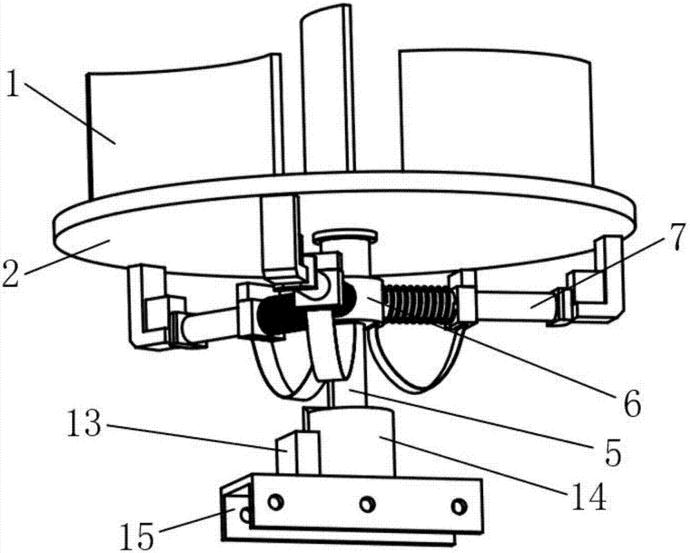
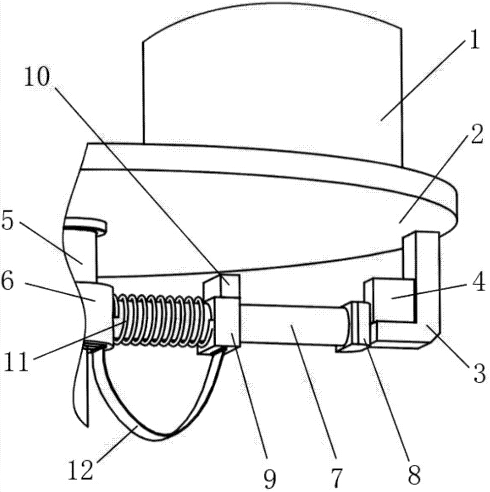
[0018] The purpose of the present invention is achieved through the following technical solutions: a piezoelectric wind energy collection device applied in a high-voltage power grid, comprising a turntable 2, a main shaft 5 and a base 14, and the base 14 is provided with a rectification energy storage device 13 , the center of the base 14 is provided with an upright main shaft 5, the bottom of the base 14 is provided with a door-shaped connector 15, the center of the turntable 2 is provided with a through hole, and the outer ring of the bearing is fixed by interference fit with the edge of the through hole at the center of the turntable 2, The inner ring and the upper part of the main shaft 5 have an interference fit, and three tile-shaped blades 1 are evenly distributed on the surface perpendicular to the surface of the turntable 2. T...


PUM


Abstract

The invention discloses a piezoelectric wind energy collecting device applied in a high-voltage grid, and belongs to the technical field of the wind energy collection. A substrate is provided with a main shaft and a gate-type connector. An outer circle of a bearing and a through hole edge of a turntable center are fixed through the interference fit, and an inner circle is in the interference fit with the upper part of the main shaft. Three tile-shaped blades are uniformly distributed on the upper surface of a plate face perpendicular to the turntable. The top of an L-shaped bracket is fixed with the edge lower surface of the plate face perpendicular to the turntable. Three L-shaped brackets are uniformly distributed in 120 degrees. The right-angle inner side of the L-shaped brackets is provided with a first magnet. The middle of the main shaft is provided with an annular connector. One end of a cylindrical polish rod is circumferentially and radially fixed with the annular connector, and the other end is fixed with the horizontal ends of the L-shaped brackets through a limiting block. A slider of which the upper part is provided with a second magnet is in the clearance fit with thecylindrical polish rod. One end of a spring is connected with the annular connector, and the other end is connected with the slider. The spring is coaxially installed with the polish rod. One end ofa flexible piezoelectric material is fixed with the annular connector, and the other end is fixed with the inner side of the slider.

Description

technical field [0001] The invention belongs to the technical field of wind energy collection. Background technique [0002] In the construction of smart grid, a large number of wireless sensors are used for grid detection. At present, it is difficult to use grid power to power sensors. Wireless sensors in the grid rely on electronic batteries for power supply. There are problems such as manual replacement of batteries, large amount of waste batteries, and difficult disposal. Harvesting ambient energy to realize self-powering of sensors is an effective solution to such problems. As a clean and renewable energy, wind energy widely exists in every part of nature and has huge potential energy. Piezoelectric energy harvesters using wind energy have the advantages of simple structure, small size, high output energy density, easy integration, and no electromagnetic interference. Therefore, wind energy harvesters based on piezoelectricity can better convert wind energy into elect...

Claims


Application Information

Patent Timeline
Patent Type & Authority Applications(China)
IPC IPC(8): F03D9/25H02N2/18
CPCH02N2/185F03D9/255Y02E10/72
Inventor 张祖涛唐民丰管奇卉刘继宗潘宏烨漆令飞刘治勇潘亚嘉
Owner SOUTHWEST JIAOTONG UNIV
Why Eureka
Try Eureka