
Magnetic flux-adjustable magnetic gear composite motor

A compound motor and magnetic gear technology, which is applied in the direction of motors, magnetic circuits, electromechanical devices, etc., can solve the problems of low output torque of hybrid excitation motors, and achieve the effects of brushless, performance improvement, and simple structure

Inactive Publication Date: 2018-04-24
HARBIN UNIV OF SCI & TECH
View PDF7 Cites 3 Cited by
  • Summary
  • Abstract
  • Description
  • Claims
  • Application Information

AI Technical Summary

Problems solved by technology

[0005] The present invention is to solve the problem of small output torque of hybrid excitation motor, and the present invention provides a magnetic flux adjustable magnetic gear composite motor

Method used


Image

  • Magnetic flux-adjustable magnetic gear composite motor
  • Magnetic flux-adjustable magnetic gear composite motor
  • Magnetic flux-adjustable magnetic gear composite motor

Examples


specific Embodiment approach 1

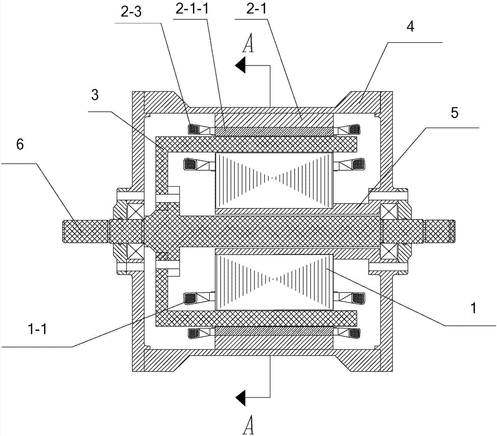
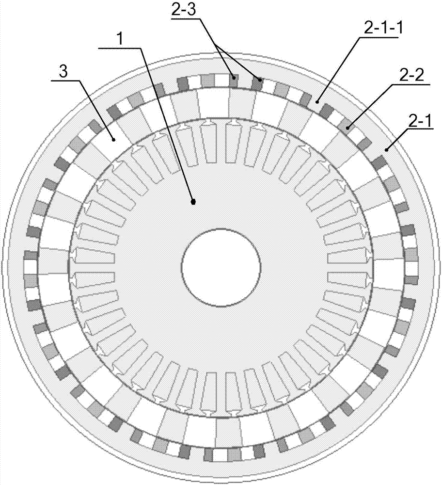
[0032] Specific implementation mode one: see Figure 1 to Figure 5 This embodiment is described. The flux-adjustable magnetic gear composite motor in this embodiment includes an inner stator 1, an outer stator 2 and a cup-shaped rotor 3. The three are coaxially arranged and located in the casing 4. The cup-shaped rotor 3 is located between the inner stator 1 and the outer stator 2;

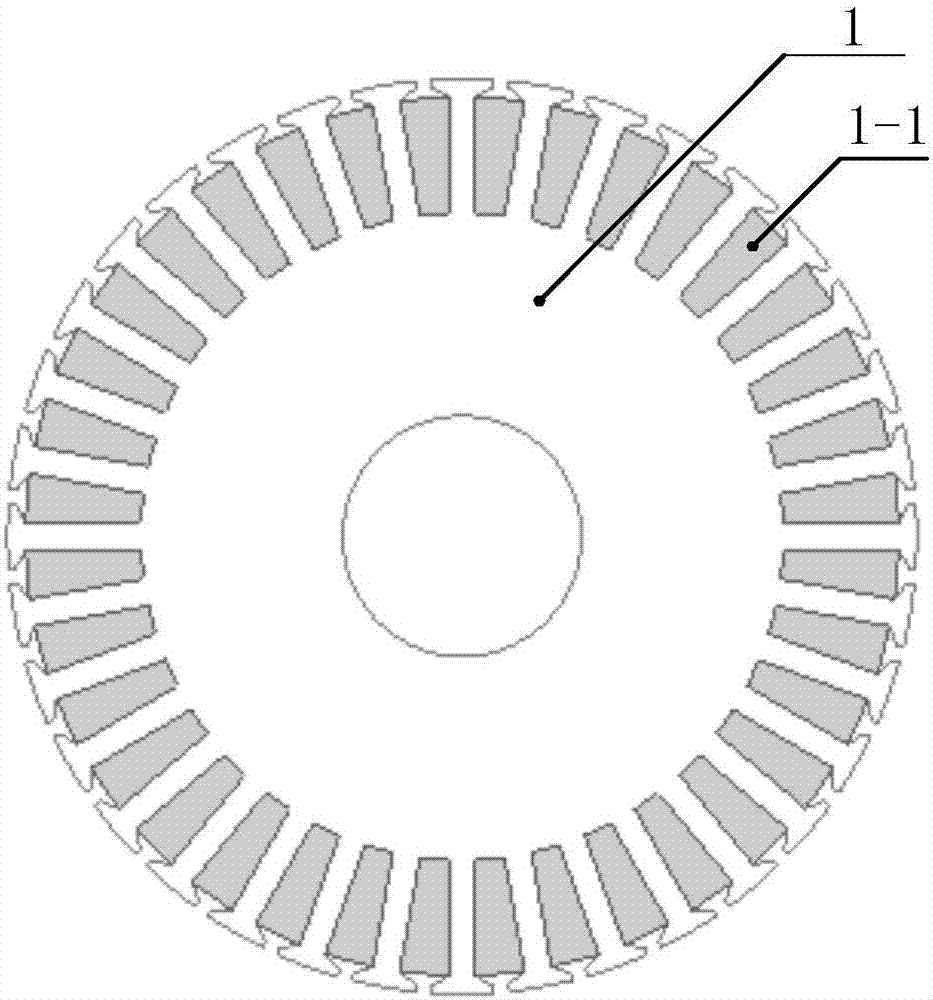
[0033] The inner stator 1 is fixed on the extension base 5 of the front cover of the casing 4, and the inner stator 1 is wound with an inner stator armature winding 1-1;

[0034] There are air gaps between the inner stator 1 and the cup rotor 3, and between the cup rotor 3 and the outer stator 2;

[0035] The cup-shaped rotor 3 is fixed on the main shaft 6, and the main shaft 6 runs through the front and rear end covers of the casing 4 and the bottom end of the cup-shaped rotor 3, and is rotatably connected with the front and rear end covers of the casing 4. Bottom fixed connection;

[0036] Th...

specific Embodiment approach 2

[0045] Specific implementation mode two: see Figures 1 to 6 This embodiment is described. The difference between this embodiment and the magnetic flux adjustable magnetic gear compound motor described in the first embodiment is that the side wall of the cup-shaped rotor 3 is composed of a magnetically conductive block 3-1 and a non-magnetically conductive block 3-1. 2 are arranged alternately.

specific Embodiment approach 3

[0046] Specific implementation mode three: see Figures 1 to 6 This embodiment is described. The difference between this embodiment and the magnetic flux adjustable magnetic gear compound motor described in the second embodiment is that the number of the outer stator teeth 2-1-1 is the same as that of the outer stator permanent magnets 2-2. The same number is N, N is an integer;

[0047] When the inner stator 1 is energized and running, the number of pole pairs of the rotating magnetic field generated is P1, and P1 is an integer;

[0048] The number of pole pairs of the magnetic field formed by the outer stator permanent magnet 2-2 on the outer stator 2 is P2, and P2 is an integer;

[0049] Satisfied condition: P2=|m P1+kN|, wherein, m=1, 3, 5, . . . , +∞; k=0, ±1, ±2, . . . , ±∞.

[0050] In this embodiment, when m=1, k=-1, the air-gap harmonic magnetic field modulated by the magnetic ring (that is: cup-shaped rotor 3) is the strongest, and at this time, the magnetic field ...


PUM


Abstract

The invention relates to a magnetic flux-adjustable magnetic gear composite motor and belongs to the hybrid excitation composite motor field. With the magnetic flux-adjustable magnetic gear compositemotor of the invention adopted, the problem of the small output torque of a hybrid excitation motor can be solved. According to the motor of the present invention, a cup-shaped rotor is adopted as a magnetic adjusting ring to adjust a magnetic field between the cup-shaped rotor and an inner stator and a magnetic field between the cup-shaped rotor and an outer stator; the outer stator includes an outer stator core, outer stator permanent magnets and an outer stator direct-current excitation winding; the inner side wall of the outer stator core is uniformly provided with outer stator teeth circumferentially; the outer stator teeth are wound with the outer stator direct-current excitation winding; the outer stator direct-current excitation winding is used for letting in direct-current excitation pulses; each outer stator permanent magnet is arranged between two adjacent outer stator teeth with gaps left between the corresponding outer stator permanent magnet and the two outer stator teeth; and the outer stator magnets are radially magnetized. The magnetic flux-adjustable magnetic gear composite motor of the present invention is mainly applied to electric vehicles.

Description

technical field [0001] The invention relates to the field of hybrid excitation compound motors. Background technique [0002] With the continuous improvement of the performance of rare earth permanent magnet materials, permanent magnet motors characterized by high efficiency and high power density have developed rapidly, and have been widely used in many industrial fields such as aviation, aerospace, ships, automobiles, and machine tools. It has greatly accelerated the pace of my country's industrial modernization, and effectively promoted the realization of my country's energy-saving and emission-reduction strategic goals. [0003] The air gap magnetic field of traditional permanent magnet motors is difficult to adjust, which leads to narrow constant power area and limited speed regulation range during electric operation; voltage regulation and fault demagnetization are difficult during power generation operation. When field weakening is required, a continuous d-axis field ...

Claims


Application Information

Patent Timeline
Patent Type & Authority Applications(China)
IPC IPC(8): H02K1/27H02K1/16
CPCH02K1/165H02K1/2786H02K2201/03Y02T10/64
Inventor 谢颖华邦杰黑亮声张晓明
Owner HARBIN UNIV OF SCI & TECH
Learn More