Reaction container capable of reducing reaction time of chemical raw materials

A reaction vessel and reaction time technology, applied in chemical/physical/physical-chemical stationary reactors, chemical instruments and methods, chemical/physical processes, etc., can solve the problems of long reaction period and low industrial production efficiency, and achieve the The effect of heat dissipation, ensuring reaction temperature, and accelerating mixing

Pending Publication Date: 2018-04-27
CHENGDU OLYMVAX BIOPHARM
View PDF4 Cites 0 Cited by
  • Summary
  • Abstract
  • Description
  • Claims
  • Application Information

AI Technical Summary

Problems solved by technology

[0003] When the reactor is used as an evaporation container, when the evaporated main liquid is viscous, the reaction cycle is long, resulting in low industrial production efficiency

Method used


Image

  • Reaction container capable of reducing reaction time of chemical raw materials

Examples


Embodiment 1

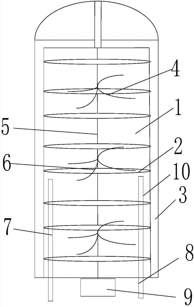
[0020] Such as figure 1 Shown, a kind of reaction container that shortens the reaction time of chemical raw materials, comprises reactor main body 1, and reactor main body 1 is hollow cylinder structure, is provided with reaction vessel 10 in reactor main body 1, and reaction vessel 10 and reactor main body 1 A vacuum cavity 3 is arranged between the inner walls, and a serpentine coil 2 is arranged inside the reaction vessel 10, and the serpentine coil 2 is arranged around the inner wall of the reaction vessel 10; the reaction vessel 10 is provided with a rotating shaft 5, and the rotating shaft The rotating blade group 4 is arranged on the 5, the lower end of the rotating shaft 5 is connected with the driving motor 9, and the driving motor 9 is connected with the frequency converter.

[0021] Reactor main body 1 described in the present embodiment is the main vessel that carries out raw material reaction, and the container of concrete realization is reaction vessel 10, and va...

Embodiment 2

[0025] The present embodiment is further defined on the basis of the embodiment. The bottom end of the reaction vessel 10 also has a first air inlet pipe 7 and a second air inlet pipe 8. The first air inlet pipe 7 and the second air inlet pipe 8 are connected from the reaction vessel 10 Insert at the bottom.

[0026] The function of the first inlet pipe 7 and the second inlet pipe 8 is to add gas such as air into the reaction vessel 10 to promote the boiling degree of the reaction raw materials in the reaction vessel 10 . Wherein, the first air intake pipe 7 and the second air intake pipe 8 are communication pipe structures. Other gas flow channels are also possible.

Embodiment 3

[0028] The difference between this embodiment and the above embodiments is that the distance between the position where the first air inlet pipe 7 is inserted into the reaction vessel 10 and the bottom of the reaction vessel 10 is 1 / 3-2 / 3 of the height of the reaction vessel 10 . The distance between the position where the second air inlet pipe 8 is inserted into the reaction vessel 10 and the bottom of the reaction vessel 10 is 1 / 5-2 / 5 of the height of the reaction vessel 10 .

[0029] Here, the first gas inlet pipe 7 and the second gas inlet pipe 8 are installed in the position of the reaction vessel 10, and the gas is passed through the first gas inlet pipe 7 and the second gas inlet pipe 8, and the gas is passed into different positions. The gas introduced can accelerate the boiling degree of the reaction raw materials in the reaction vessel 10. The specific structural shape of the reaction vessel 10 described in this embodiment is a hollow cylinder, and is located inside ...


PUM


Abstract

The invention discloses a reaction container capable of reducing reaction time of chemical raw materials. The reaction container includes a reaction kettle body which has a hollow cylindrical structure. A reaction container is arranged in the reaction kettle body, wherein a vacuum cavity is formed between the reaction container and the inner wall of the reaction kettle body. A snakelike coil pipeis arranged in the reaction container and is disposed on the inner wall of the reaction container in a circular structure. A rotary shaft is arranged in the reaction container and is provided with a rotary blade group. The lower end of the rotary shaft is connected to a driving motor which is connected to a frequency converter. In the reaction container, the snakelike coil pipe is arranged, wherein high temperature gas flows in the snakelike coil pipe, so that complete heat exchange with a liquid raw material in the reaction container is achieved. The structure has advantages on heating the liquid raw material in the reaction container, thus increasing boiling degree.

Description

technical field [0001] The invention relates to the technical field of chemical equipment, in particular to a reaction vessel for shortening the reaction time of chemical raw materials. Background technique [0002] The reaction kettle is a container for physical or chemical reactions. Through the structural design and parameter configuration of the container, the heating, evaporation, cooling and low-speed mixing functions required by the process are realized. And the reaction kettle is widely used in the process of petroleum, chemical, rubber, pesticide, dye, medicine, food and other pressure vessels, and the general material is stainless steel. [0003] When the reaction kettle is used as an evaporation container, when the evaporated main liquid is viscous, the reaction cycle is long, resulting in low industrial production efficiency. [0004] Based on this, research and development of a reaction vessel that shortens the reaction time of chemical raw materials. Content...

Claims


Application Information

Patent Timeline
Patent Type & Authority Applications(China)
IPC IPC(8): B01J19/18B01J19/00
CPCB01J19/0053B01J19/0066B01J19/18B01J2219/00081
Inventor 周先美李新荣帅志全刘述清
Owner CHENGDU OLYMVAX BIOPHARM
Why Eureka
Try Eureka