Laser and electrolytic combined machining method and device

A compound processing and coupling device technology, applied in laser welding equipment, metal processing equipment, manufacturing tools, etc., can solve the problems of difficult processing of complex contours, large depth-to-diameter ratio fine structures, insufficient processing depth, large processing taper, etc., to achieve high Surface finish, good surface quality, low taper effect

Active Publication Date: 2018-04-27
NINGBO INST OF MATERIALS TECH & ENG CHINESE ACADEMY OF SCI
View PDF9 Cites 13 Cited by
  • Summary
  • Abstract
  • Description
  • Claims
  • Application Information

AI Technical Summary

Problems solved by technology

Despite the above-mentioned progress, the research on laser and electrolytic composite processing is still in its infancy, and there are still shortcomings such as insufficient processing depth (≤1mm), large processing taper, and poor reliability.
The laser-assisted jet

Method used


Image

  • Laser and electrolytic combined machining method and device
  • Laser and electrolytic combined machining method and device
  • Laser and electrolytic combined machining method and device

Examples


Embodiment 1

[0111] Embodiment 1 laser and electrolytic composite processing

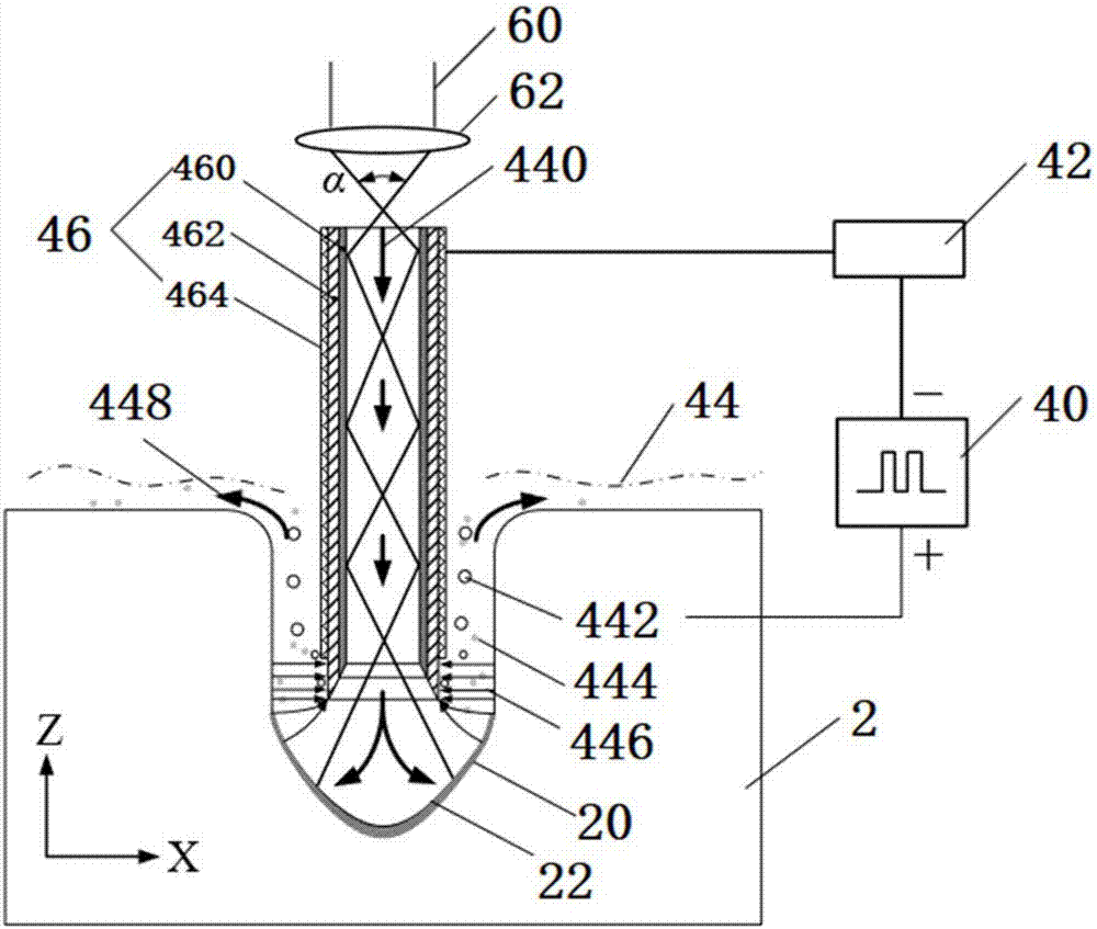
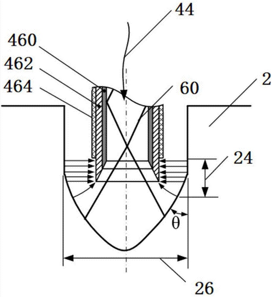
[0112] In this embodiment, based on laser and electrolytic composite processing, the schematic diagrams involved are as follows figure 1 and figure 2 shown. Specifically include the following steps:

[0113] (1) The tool electrode 46 includes a metal conduit 462 and a liquid-core optical fiber 460 installed inside it, and the side of the metal conduit is coated with an insulating layer 464; the liquid-core optical fiber is coaxially located in the metal conduit.

[0114] Among them, the liquid core optical fiber is TEFLON AF2400 (DUPONT) purchased from BIOGENERAL company in the United States, and the optical refractive index is about n 1 = 1.29;

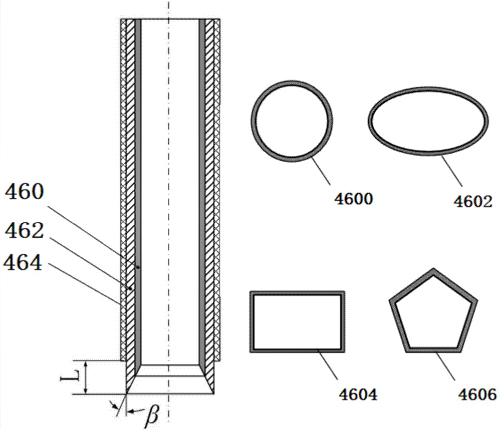
[0115] The metal conduit 462 is made of stainless steel, and its side is coated with an insulating layer by electrostatic spraying from top to bottom. The angle β between the inner wall and the outer wall is 30°.

[0116] (2) The electrolytic solution 44 flows f...

Embodiment 2

[0126] Example 2 Laser Interventional Micro Electrolytic Machining

[0127] The difference between the laser-intervened micro-electrolytic machining method in this embodiment and that in Embodiment 1 is:

[0128] The metal conduit 462 is made of stainless steel, and its side is coated with an insulating layer by electrostatic spraying from top to bottom. The angle β between the inner wall and the outer wall is 70°.

[0129] The interfaces of the liquid-core optical fiber, the tool electrode and the metal conduit are rectangular.

[0130] Wherein, the tool electrode 46 is clamped above the workpiece 2, and the initial machining gap between the end of the tool electrode and the workpiece processing surface is set to be about 1 mm; the feed speed of the tool electrode is 100 μm / s.

[0131] The energy density of the laser beam 60 acting on the processed surface of the workpiece 2 is 1.5-5GW / cm 2 ;The flow rate of electrolyte is 0.1~0.5m 3 / h.

[0132] The pore structure is ob...

Embodiment 3

[0133] Example 3 Laser Interventional Micro Electrolytic Machining

[0134] The difference between the laser-intervened micro-electrolytic machining method in this embodiment and that in Embodiment 1 is:

[0135] The liquid-core optical fiber is a TEFLON AF capillary purchased from BIOGENERAL.

[0136] The metal conduit 462 is made of stainless steel, and its side is coated with an insulating layer by electrostatic spraying from top to bottom. The angle β between the inner wall and the outer wall is 45°.

[0137] The interfaces of the liquid-core optical fiber, the tool electrode and the metal conduit are rectangular.

[0138] Wherein, the tool electrode 46 is clamped above the workpiece 2, and the initial machining gap between the end of the tool electrode and the workpiece processing surface is set to be about 0.5 mm; the feed speed of the tool electrode is 50 μm / s.

[0139] The energy density of the laser beam 60 acting on the processed surface of the workpiece 2 is 5-10...


PUM

PropertyMeasurementUnit
The inside diameter ofaaaaaaaaaa
Outer diameteraaaaaaaaaa

Abstract

The invention discloses a laser and electrolytic combined machining method. The method at least comprises the following steps that a tool electrode and a workpiece to be machined are connected with the negative electrode and the positive electrode of a power supply correspondingly; lasers and an electrolyte are coupled and transmitted to a machining area of the workpiece to be machined through thetool electrode; and laser and electrolytic combined machining is carried out after the power supply is switched on, and the tool electrode is fed to the workpiece to be machined so as to obtain a target machining structure. Meanwhile, the invention provides a laser and electrolytic combined machining device. The method and device are beneficial to high-efficiency machining of large-depth-to-diameter-ratio micro-structures such as deep-small holes with good surface quality and high precision.

Description

technical field [0001] The application relates to a laser and electrolytic composite processing method and a device thereof, which belong to the field of micro electrolytic processing. Background technique [0002] Laser processing technology uses laser beam as the main tool to realize the removal and processing of workpiece materials through the photothermal effect or photochemical effect of light and materials. It has the advantages of high energy density, high resolution and high processing efficiency. Traditional laser processing has high processing efficiency in surface processing, but has disadvantages such as low processing efficiency, difficulty in processing taper control, and insufficient processing depth capability in large-depth processing. In order to improve the precision and depth of laser processing, scholars at home and abroad have proposed laser mechanical cutting composite processing technology, water-assisted laser processing technology, laser-assisted je...

Claims


Application Information

Patent Timeline
IPC IPC(8): B23H5/00B23K26/00B23K26/70
CPCB23H5/00B23K26/0093B23K26/70
Inventor 张文武王玉峰
Owner NINGBO INST OF MATERIALS TECH & ENG CHINESE ACADEMY OF SCI
Why Eureka
Try Eureka