Tool manufacturing equipment

A technology of equipment and cutter body, applied in the field of cutter preparation equipment, can solve the problems of cutter deformation, low welding efficiency, high labor intensity, etc., and achieve the effects of reducing weight, convenient movement and installation, and improving pushing efficiency.

Active Publication Date: 2018-04-27
雅安恒成精密刀具有限公司
View PDF12 Cites 0 Cited by
  • Summary
  • Abstract
  • Description
  • Claims
  • Application Information

AI Technical Summary

Problems solved by technology

At present, manual welding is generally used. There are many defects in manual welding: for example, it is difficult to grasp the temperature and time of welding. If the temperature is low or the time is short, the welding may not be firm; Too much tool deformation
[0006] 1. The conveying of the cutter body cannot be carried out continuously, which affects the preparation efficiency of the entire cutter;
[0007] 2. When the cutter body and the blade are installed, the position of the cutter body needs to be manually adjusted so that the blade is installed in the slot of the cutter body, which is labor-intensive and inefficient;
[0008] 3. When the blade is installed, it is necessary to manually remove the blade for installation, which is labor-intensive, not only poor in safety, but also low in efficiency;
[0009] 4. The blade welding process is complicated and the welding efficiency is low

Method used


Image

  • Tool manufacturing equipment
  • Tool manufacturing equipment
  • Tool manufacturing equipment

Examples


Embodiment 1

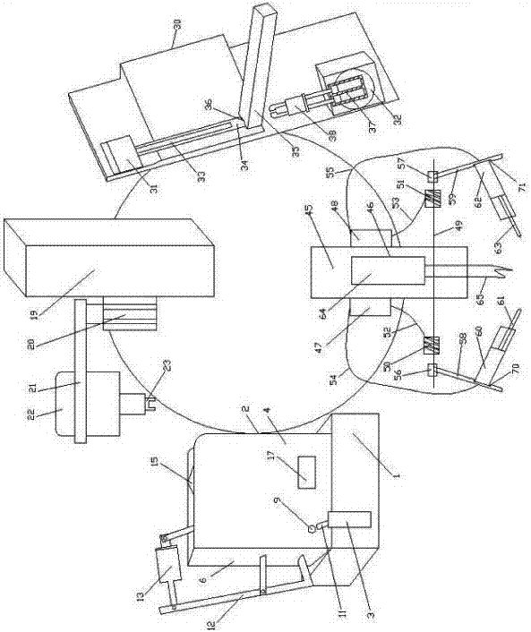
[0073] A cutting tool preparation device, comprising a cutting device pushing device, a cutting device aligning device, a blade placing device and a blade welding device;

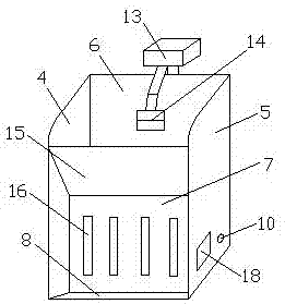
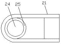
[0074] The cutter body pushing device includes a mounting seat 1, on which a cutter body reserve bin 2 and a pusher cylinder 3 are fixed, and the cutter body reserve bin 2 includes a first side plate 4, a second side plate fixedly connected together. Two side plates 5, the first baffle plate 6, the second baffle plate 7 and the base plate 8, the bottom of the first side plate 4 has a first through hole 9, and the bottom of the second side plate 5 has a first through hole 9. The second through hole 10 corresponding to the hole 9, the pusher cylinder 3 is fixed with a push rod 11, and the push rod 11 is on the same level as the first through hole 9;

[0075]Described cutter body aligning device comprises support 19, and described support 19 is fixed with lift cylinder 20, and described lift cylinder 20 is hor...

Embodiment 2

[0080] A cutting tool preparation device, comprising a cutting device pushing device, a cutting device aligning device, a blade placing device and a blade welding device;

[0081] The cutter body pushing device includes a mounting seat 1, on which a cutter body reserve bin 2 and a pusher cylinder 3 are fixed, and the cutter body reserve bin 2 includes a first side plate 4, a second side plate fixedly connected together. Two side plates 5, the first baffle plate 6, the second baffle plate 7 and the base plate 8, the bottom of the first side plate 4 has a first through hole 9, and the bottom of the second side plate 5 has a first through hole 9. The second through hole 10 corresponding to the hole 9, the pusher cylinder 3 is fixed with a push rod 11, and the push rod 11 is on the same level as the first through hole 9;

[0082] Described cutter body aligning device comprises support 19, and described support 19 is fixed with lift cylinder 20, and described lift cylinder 20 is ho...

Embodiment 3

[0088] A cutting tool preparation device, comprising a cutting device pushing device, a cutting device aligning device, a blade placing device and a blade welding device;

[0089] The cutter body pushing device includes a mounting seat 1, on which a cutter body reserve bin 2 and a pusher cylinder 3 are fixed, and the cutter body reserve bin 2 includes a first side plate 4, a second side plate fixedly connected together. Two side plates 5, the first baffle plate 6, the second baffle plate 7 and the base plate 8, the bottom of the first side plate 4 has a first through hole 9, and the bottom of the second side plate 5 has a first through hole 9. The second through hole 10 corresponding to the hole 9, the pusher cylinder 3 is fixed with a push rod 11, and the push rod 11 is on the same level as the first through hole 9;

[0090] Described cutter body aligning device comprises support 19, and described support 19 is fixed with lift cylinder 20, and described lift cylinder 20 is ho...


PUM


Abstract

The invention discloses tool manufacturing equipment, and belongs to the field of tool machining and manufacturing. The tool manufacturing equipment is characterized in that a tool body pushing devicecomprises an installation base, and a tool body storage bin and a tool pushing cylinder are fixed to the installation base; a tool body alignment device comprises a support, a lifting cylinder is fixed to the support, a supporting frame is fixed to the lifting cylinder, and a stepping motor is fixed to the supporting frame; a blade installation device comprises a fixed base, a blade pushing cylinder and a rotating cylinder are arranged on the fixed base, a double-shaft cylinder is fixed to the rotating cylinder, and a parallel clamp is fixed to the double-shaft cylinder; and a blade welding device comprises a vertical base, an electromagnetic heater is fixed to the vertical base, a first wire feeder is fixed to one side of the vertical base, and a second wire feeder is fixed to the otherside of the vertical base. According to the tool manufacturing equipment, tool bodies can be conveyed continuously, a tool body insertion groove can be rapidly aligned with the installation position corresponding to a blade, and the blade can be taken out rapidly to be installed; and the contact portions of the blade and the tool body can be welded from the two sides at the same time, and the welding uniformity and the welding effect are ensured.

Description

technical field [0001] The invention relates to the technical field of cutting tool processing and preparation, in particular to a cutting tool preparation equipment. Background technique [0002] A cutting tool is a tool used for cutting in mechanical manufacturing, also known as a cutting tool. The vast majority of knives are for machine use, but some are also for hand use. Knives for cutting wood are called woodworking knives. Knives are usually composed of two parts: a blade and a cutter body. The blade is made of more expensive cemented carbide or high-speed steel. High-speed steel is a tool steel with high hardness, high wear resistance and high heat resistance, also known as high-speed tool steel or front steel, commonly known as white steel. The cutter body is made of ordinary steel, and the two parts are welded together with solder. At present, manual welding is generally used. There are many defects in manual welding: for example, it is difficult to grasp the t...

Claims


Application Information

Patent Timeline
IPC IPC(8): B23K3/00B23K3/06B23K3/08
CPCB23K3/00B23K3/063B23K3/08
Inventor 金绍龙
Owner 雅安恒成精密刀具有限公司
Why Eureka
Try Eureka