Pipe support
A pipe support and support rod technology, applied in the field of pipe supports, can solve the problems of large occupied space and difficult transportation, and achieve the effects of reducing occupied space, saving time, and facilitating forklift transportation
- Summary
- Abstract
- Description
- Claims
- Application Information
AI Technical Summary
Problems solved by technology
Method used
Image

Examples
Embodiment 1
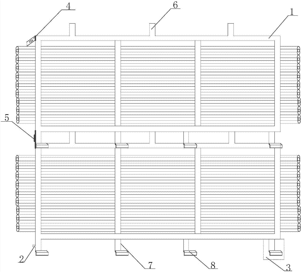
[0028] see figure 1 As shown, is a schematic structural diagram of the pipe support provided in the embodiment of the present application. The pipe bracket includes several bracket bodies 1 sequentially connected from top to bottom, and adjacent bracket bodies 1 are connected by snap joints 3; wherein,
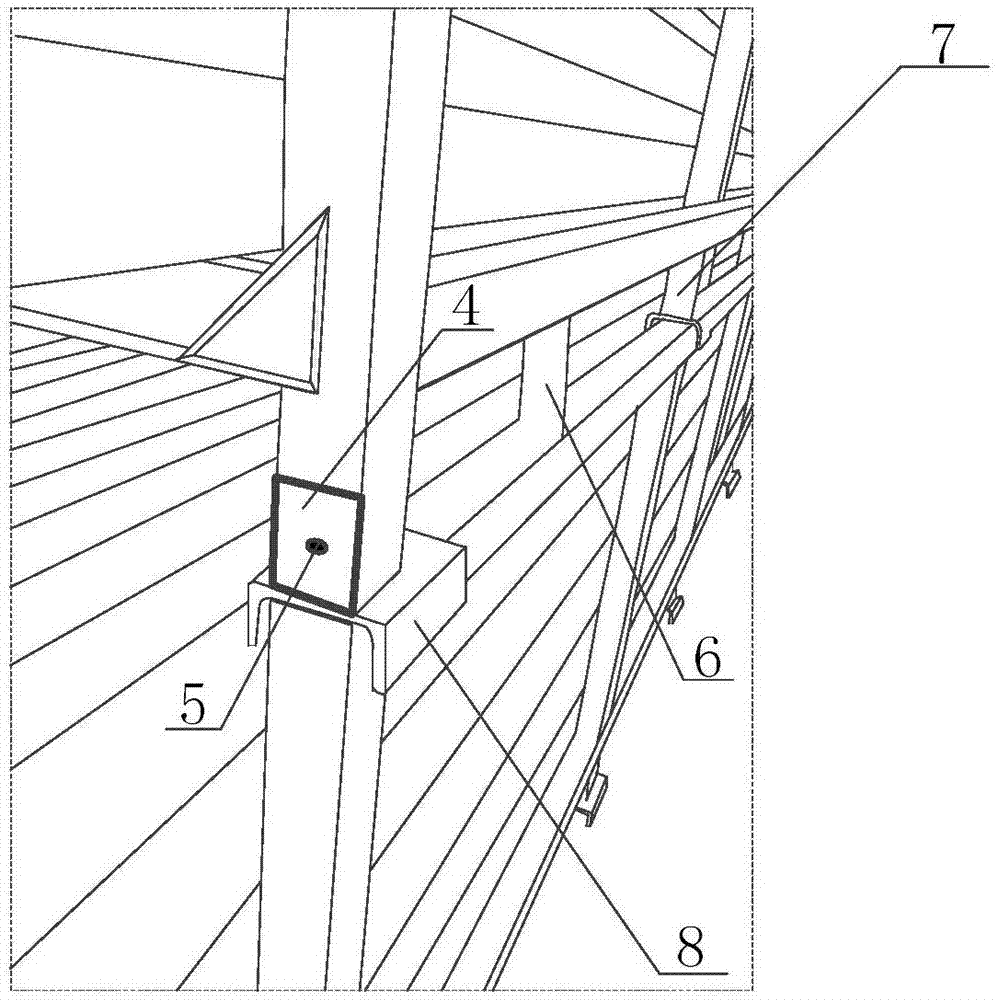
[0029] The clamping part 3 includes a support rod 7 fixedly arranged at the bottom of the support body 1, one end of the support rod 7 is fixedly connected with the support body 1, and the other end of the support rod 7 is vertically fixed with a clamp slot 8;
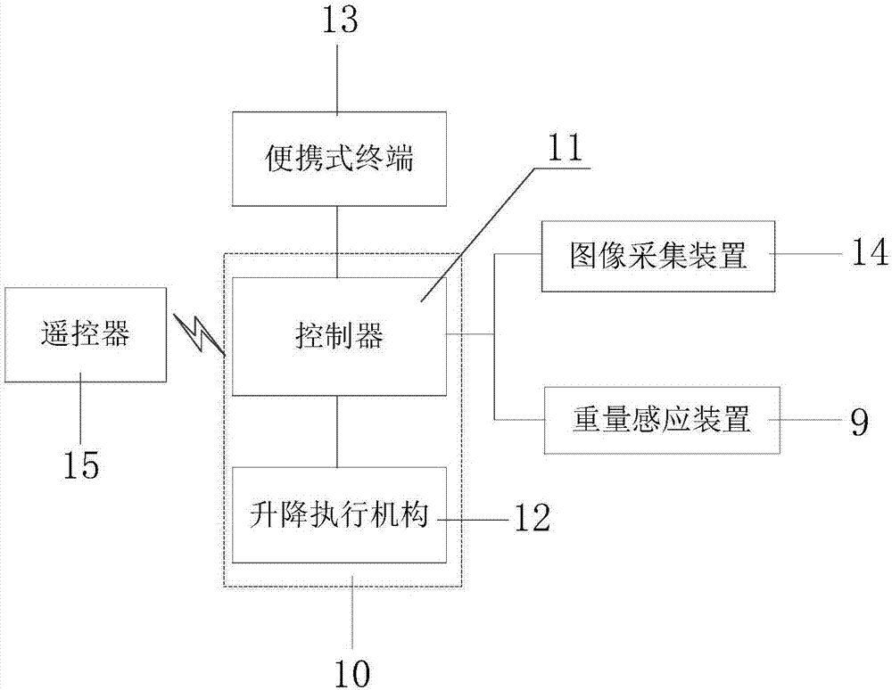
[0030] Each of the bracket bodies 1 is equipped with a weight sensing device 9, see figure 2 As shown in , it is a connection block diagram of the control components of the pipe support provided in the embodiment of the present application. The weight sensing devices 9 are all connected to the lifting control device 10; the lifting control device 10 includes a controller 11 and a lifting actuator 12, the controller...
Embodiment 2
[0033] see figure 1 , figure 2 and image 3 As shown, the pipe bracket includes several bracket bodies 1 sequentially connected from top to bottom, and the adjacent bracket bodies 1 are connected by a clamping part 3; wherein,
[0034] The clamping part 3 includes a support rod 7 fixedly arranged at the bottom of the support body 1, one end of the support rod 7 is fixedly connected with the support body 1, and the other end of the support rod 7 is vertically fixed with a clamp slot 8;
[0035] Each of the bracket bodies 1 is equipped with a weight sensing device 9, and the weight sensing device 9 is connected with a lifting control device 10; the lifting control device 10 includes a controller 11, a lifting actuator 12, and the controller 11 is disposed inside the lift control device 10 , and the controller 11 is connected to the lift actuator 12 .
[0036] Optionally, a first protruding portion 2 is provided on one side of the support rod 7, and the adjacent bracket bodi...
Embodiment 3
[0042] see figure 1 , figure 2 and image 3 As shown, the pipe bracket includes several bracket bodies 1 sequentially connected from top to bottom, and the adjacent bracket bodies 1 are connected by a clamping part 3; wherein,
[0043]The clamping part 3 includes a support rod 7 fixedly arranged at the bottom of the support body 1, one end of the support rod 7 is fixedly connected with the support body 1, and the other end of the support rod 7 is vertically fixed with a clamp slot 8;
[0044] Each of the bracket bodies 1 is equipped with a weight sensing device 9, and the weight sensing device 9 is connected with a lifting control device 10; the lifting control device 10 includes a controller 11, a lifting actuator 12, and the controller 11 is disposed inside the lift control device 10 , and the controller 11 is connected to the lift actuator 12 .
[0045] Optionally, the top of the bracket body 1 is provided with a supporting second raised portion 6 , and the height of t...
PUM
 Abstract
Description
Claims
Application Information
 - R&D
- Intellectual Property
- Life Sciences
- Materials
- Tech Scout
- Unparalleled Data Quality
- Higher Quality Content
- 60% Fewer Hallucinations
Browse by: Latest US Patents, China's latest patents, Technical Efficacy Thesaurus, Application Domain, Technology Topic, Popular Technical Reports.
© 2025 PatSnap. All rights reserved.Legal|Privacy policy|Modern Slavery Act Transparency Statement|Sitemap|About US| Contact US: help@patsnap.com