Vibrating wire sensor excitation optimization method and vibrating wire acquisition device

A technology of vibrating wire sensor and optimization method, which is applied in the direction of measuring device, measurement of force by measuring the frequency change of the stressed vibrating element, instruments, etc., which can solve the problem that the measurement accuracy of the vibrating wire sensor is easily disturbed by the ambient temperature, and the acquisition device Does not support long-distance data transmission, metal string vibration duration is short, etc., to achieve the effect of shortening the start-up time and detection time, enhancing anti-interference ability, and prolonging the vibration duration

Inactive Publication Date: 2018-04-27
SOUTHEAST UNIV
View PDF5 Cites 11 Cited by
  • Summary
  • Abstract
  • Description
  • Claims
  • Application Information

AI Technical Summary

Problems solved by technology

However, these two excitation methods have great limitations: in the high-voltage pulse excitation method, the vibration duration of the metal string is short, the signal is not easy to pick up, the measurement accuracy is poor, and the high voltage is easy to accelerate the aging of the metal string, resulting in vibration. Damaged string sensor
However, there ...

Method used


Image

  • Vibrating wire sensor excitation optimization method and vibrating wire acquisition device
  • Vibrating wire sensor excitation optimization method and vibrating wire acquisition device
  • Vibrating wire sensor excitation optimization method and vibrating wire acquisition device

Examples


Embodiment Construction

[0034] Below in conjunction with accompanying drawing, technical scheme of the present invention is described in further detail:

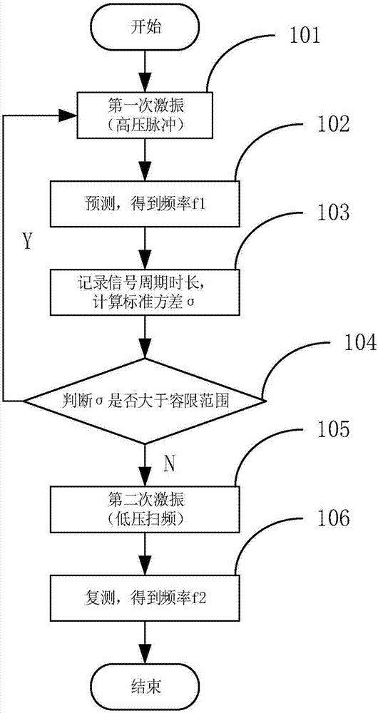
[0035] Such as figure 1 As shown, the vibrating wire sensor excitation optimization method of the present invention includes the following steps:

[0036] Step 101: Excitation for the first time: Excite the selected vibrating wire sensor once by means of high-voltage pulse excitation.

[0037] Step 102: Prediction: amplify and filter the collected signal of the vibrating wire measured by the vibrating wire sensor, and measure its signal frequency to obtain the resonant frequency f1 of the vibrating wire. Since the high-voltage pulse excitation method has the disadvantages of short duration of metal string vibration, difficult signal pickup, and poor measurement accuracy, the frequency f1 obtained by the high-voltage pulse excitation method is only a rough value close to the exact resonance frequency. If you want to improve Its frequency measurement...


PUM


Abstract

The invention discloses a vibrating wire sensor excitation optimization method and a vibrating wire acquisition device, which belong to the technical field of sensor detection control. According to the vibrating wire sensor excitation optimization method disclosed in the invention, fast onset, short detection time and high precision can be realized when the vibrating wire sensor is detected. The excitation optimization method combines two excitation modes of high voltage pulses and low voltage sweep frequency, the excitation reliability is improved, and the method is applicable to measurementon various kinds of vibrating wire sensors. The vibrating wire acquisition device which uses the vibrating wire sensor excitation optimization method mainly comprises a power management circuit, a vibrating wire excitation sampling circuit, a micro control unit MCU, a burning debugging interface, a wireless communication module and a temperature and humidity sensor module. The method is high-efficiency and convenient, and the corresponding device is high in integration, convenient in remote data transmission, low in cost and convenient in debugging.

Description

technical field [0001] The invention relates to an excitation optimization method for a vibrating wire sensor and a vibrating wire acquisition device, belonging to the technical field of sensor detection and control. Background technique [0002] The vibrating wire sensor is a sensor with a tensioned metal string as the sensitive element. When the length of the metal string is determined, changing the stress state of the metal string can change the natural vibration frequency of the metal string. Pull size. [0003] There are two types of vibrating wire sensors: one is a double coil and the other is a single coil. The double coil contains the excitation coil and the vibration pickup coil. The excitation coil is used to excite the vibrating wire and make the vibrating wire vibrate; the pickup coil is a device that converts the mechanical vibration of the vibrating wire into an induced electromotive force of the same frequency. However, there is only one coil in the single...

Claims


Application Information

Patent Timeline
IPC IPC(8): G01L1/10G01H13/00
Inventor 李冰余晶晶张林董乾刘勇王刚赵霞沈克强
Owner SOUTHEAST UNIV
Why Eureka
Try Eureka