Impact and thermal compounding test device for fiber-reinforced compound thin-walled component

A technology of fiber-reinforced composite and thin-walled components, which is applied in the testing of machines/structural components, measuring devices, vibration testing, etc. It can solve the problems of inability to apply large impact, insufficient compact structure, small thrust, etc., and achieve accurate measurement of vibration Data and impact results, the size of the impulse is convenient to control, and the effect of stable working ability

Inactive Publication Date: 2018-04-27
NORTHEASTERN UNIV
View PDF11 Cites 14 Cited by
  • Summary
  • Abstract
  • Description
  • Claims
  • Application Information

AI Technical Summary

Problems solved by technology

Its structure is simple, but its function is single, and its scope of application is extremely limited. It can only be applied to apply impact in a vertical manner. The structure is not compact. If you want to obtain a large impact, you must have a higher drop height. The object cannot be separated from the tested material in time and effectively after the impact is applied, whether it is the secondary impact caused by the rebound or the impact object itself has a considerable impact on the accuracy of the test
Patent CN200910197140-1 proposes a high-speed steel ball impact test device, which uses the principle of electromagnetic induction to accelerate the steel ball, so i

Method used


Image

  • Impact and thermal compounding test device for fiber-reinforced compound thin-walled component
  • Impact and thermal compounding test device for fiber-reinforced compound thin-walled component
  • Impact and thermal compounding test device for fiber-reinforced compound thin-walled component

Examples


Embodiment Construction

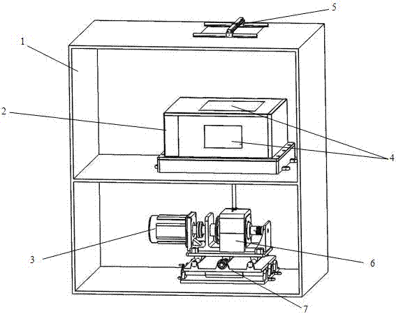
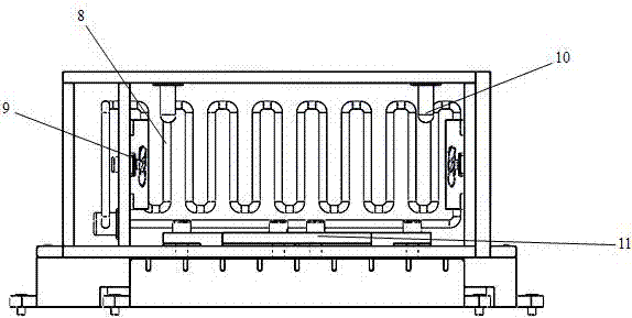
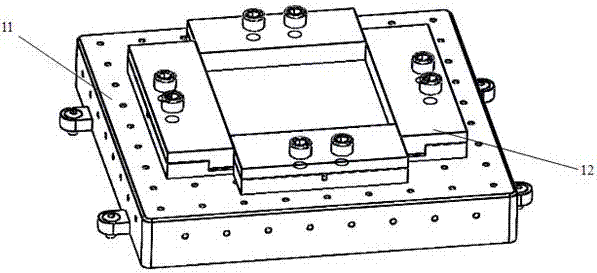
[0019] Below in conjunction with accompanying drawing and embodiment the present invention is described in further detail, as Figure 1~Figure 5 As shown, an impact and heat composite test device for fiber reinforced composite thin-walled components includes an outer box 1, a base 7 and a test box 2 arranged in the outer box 1, and a motor 3 arranged on the base 7, a rotating Accelerator 6 and conduit 13, the housing of described motor 3 is fixedly arranged on base 7, the output shaft of motor 3 is connected the power input shaft of rotary accelerator 6, and described rotary accelerator 6 comprises the motor that is fixedly arranged on base 7 The casing and the driving rotor 15 and driven rotor 16 arranged in the casing, the driving rotor 15 is fixedly sleeved on the power input shaft, the driven rotor 16 can slide axially relative to the driving rotor 15, and the driven rotor shaft is set There is an electromagnetic separator 14, the active rotor 15 and the driven rotor 16 ar...


PUM


Abstract

The invention relates to an impact and thermal compounding test device for a fiber-reinforced compound thin-walled component, which belongs to the technical field of vibration fatigue test. The devicecomprises an outer box, a base and a test box arranged in the outer box, and a motor, a rotation accelerator and a guide pipe arranged on the base, wherein the shell of the motor is fixed on the base; the output shaft of the motor is connected with the power input shaft of the rotation accelerator; the rotation accelerator comprises a housing fixed on the base and a drive rotor and a driven rotorwhich are arranged in the housing; the drive rotor fixedly sleeves the power input shaft; the driven rotor can axially slide relative to the drive rotor; an electromagnetic separator is arranged on adriven rotor shaft; meshed teeth are arranged on the drive rotor and the driven rotor; the lower end of the guide pipe is corresponding to the edge of the drive rotor; the test box is arranged abovethe guide pipe; the lower part of the test box is provided with an opening corresponding to the guide pipe; and the test box is internally provided with a rotating fan, a carbon fiber heating pipe, acooling system, a temperature sensor and a test rig.

Description

Technical field: [0001] The invention belongs to the technical field of vibration fatigue testing, in particular to an impact and heat composite testing device for fiber-reinforced composite thin-walled components. Background technique: [0002] Fiber-reinforced composite materials and their structures have high specific strength, high specific modulus, material designability, good thermal stability, and also have the advantages of large bearing capacity and light weight. They are widely used in aviation, aerospace, machinery, ships, etc. , sports equipment, electrical equipment, medicine, weapons industry and chemical industry and other fields. With the continuous improvement of modern industrial level, many fiber-reinforced composite thin-walled components, such as composite blades, composite blisks and composite cylindrical shells, often work in harsh environments such as high-speed rotation, high temperature, impact, and corrosive gas erosion. Among them, the problems o...

Claims


Application Information

Patent Timeline
IPC IPC(8): G01M7/02G01M7/06
CPCG01M7/00G01M7/06
Inventor 李晖鲍涛张绍东许卓于浩赵君凯闻邦椿
Owner NORTHEASTERN UNIV
Why Eureka
Try Eureka