
Heat dissipation method for power transformation equipment

A heat dissipation method and technology of substation equipment, which are applied in the directions of substation/distribution device casing, substation/switch layout details, and substation/switchgear cooling/ventilation, etc. Large heat dissipation area or heat exchange area, the effect of increasing the working area

Inactive Publication Date: 2018-04-27
宁波南顿电力科技有限公司
View PDF8 Cites 6 Cited by
  • Summary
  • Abstract
  • Description
  • Claims
  • Application Information

AI Technical Summary

Problems solved by technology

[0004] The purpose of the present invention is to provide a box-type substation with peripheral heat dissipation to solve the problem of low cooling efficiency of the existing box-type substation

Method used


Image

  • Heat dissipation method for power transformation equipment
  • Heat dissipation method for power transformation equipment
  • Heat dissipation method for power transformation equipment

Examples


Embodiment

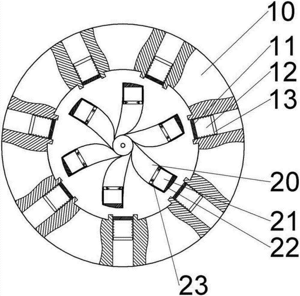
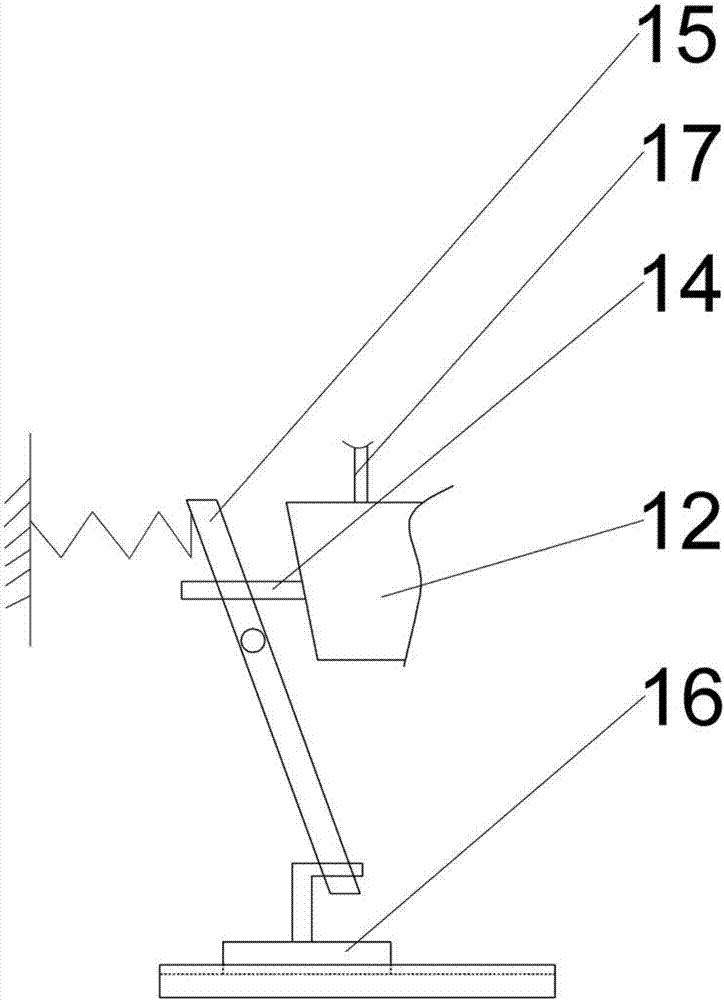
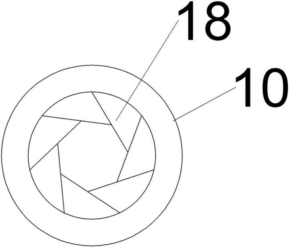
[0027] Basic as attached figure 1 As shown, the substation heat dissipation device includes a frame, and also includes cooling holes arranged on the frame. A cooling fan and a dust-proof sheet 18 for adjusting the working area of ​​the cooling hole are arranged in the cooling hole in sequence along the axial direction, wherein the cooling fan It includes a rotating shaft 33 arranged on the frame, a blade 20 fixedly connected to the rotating shaft 33, a sliding block 21 slidably arranged on the outer end of the blade 20, a tension spring 23 is arranged between the inner end of the sliding block 21 and the blade 20, and the sliding block 21 The outer end is fixed with a first magnetic body 22; a second magnetic body 11 is slidably arranged on the outer wall 10 of the cooling hole, and a top plate is fixed on the second magnetic body 11, and an air bag 12 is also fixed between the top plate and the second magnetic body 11. The second magnetic body 11 and the first magnetic body 2...


PUM


Abstract

The invention discloses a heat dissipation method for a transformation device. The heat dissipation method comprises the steps of: step 1, opening dust-proof sheets; step 2, turning on a heat dissipation fan, wherein a rotation speed of the heat dissipation fan is 1500-2500 r / min, the outer end of a blade is slidably connected with a sliding block, each sliding block can slide outwards under the action of a centrifugal force after the corresponding blade rotates, the sliding of each sliding block is bound to drive a second magnetic body, an air bag and a top plate to move outwards, the corresponding dust-proof sheet can move outwards accordingly, the upper end of a connecting rod moves outwards, the lower end of the connecting rod moves reversely so as to drive a button handle of a slide switch, and the air bag contracts to control the button handle to move reversely after the temperature is lowered, so as to reduce the rotation speed of the heat dissipation fan, and the steps are repeated to realize automatic adjustment. The heat dissipation method for the power transformation equipment can solve the problem of low heat dissipation efficiency of the existing box type transformer substation.

Description

technical field [0001] The invention relates to the technical field of substation cooling, in particular to a cooling method for substation equipment. Background technique [0002] Box-type substations are generally equipped with a lot of high and low-voltage power distribution equipment. These power distribution equipment generate a lot of heat. Therefore, box-type substations must have strong heat dissipation capabilities and good protection performance to prevent small animals from entering. [0003] In order to meet the waterproof and anti-foreign object requirements of the box-type substation, the shell structure of the box-type substation in the prior art is mostly a sealed design, and the heat dissipation performance is very poor, or the shell of the box-type substation is equipped with flat heat dissipation windows, but due to The structural defects of the flat heat dissipation window itself are poor waterproof, and it is easy to enter water in extreme rainy weather....

Claims


Application Information

Patent Timeline
IPC IPC(8): H02B1/56H02B1/28
CPCH02B1/56H02B1/28H02B1/565
Inventor 邱红光
Owner 宁波南顿电力科技有限公司
Learn More