Circuit control system for LED shadowless lamp of digital operating room

A LED shadowless lamp and circuit control technology, applied in the use of semiconductor lamps, electric light sources, electrical components, etc., can solve the problems of decreased illumination of the center spot, inconvenient operation, and low light utilization rate, etc., to achieve accurate adjustment and good use effect Effect

Inactive Publication Date: 2018-04-27
NANTONG MEDICAL DEVICES
View PDF7 Cites 2 Cited by
  • Summary
  • Abstract
  • Description
  • Claims
  • Application Information

AI Technical Summary

Problems solved by technology

However, due to the independence of its control, the traditional LED surgical shadowless lamp can only be controlled and operated on the control panel, which cannot realize integrated and intelligent management control and maintenance.
In addition, the existing LED surgical shadowless lamp also has the following defects: 1) Generally, the size of the shadowless light spot is manually adjusted through the disinfection handle, which cannot realize intelligent control and is not convenient to operate; even if there is an electric focusing method, it is also based on artificial The control of the jog button cannot achieve accurate digital adjustment; 2) The circuit structure is simple, it is difficult to realize the simultaneous existence of color temperature adjustment, cavity mirror mode, and bright mode, and the traditional color temperature adjustment generally only uses two series of high and low color temperatures Changes in the color temperature of lamp beads and color temperature can easily cause changes in illuminance; 3) Traditional LED shadowless lights are generally controlled as a whole and do not have the function of automatically detecting light occlusion, so that the light utilization rate is not high, and when there is a lot of occlusion, the illumination of the central spot will drop seriously.

Method used


Image

  • Circuit control system for LED shadowless lamp of digital operating room
  • Circuit control system for LED shadowless lamp of digital operating room

Examples


Embodiment Construction

[0015] The present invention will be further described in detail below in conjunction with the accompanying drawings and specific embodiments.

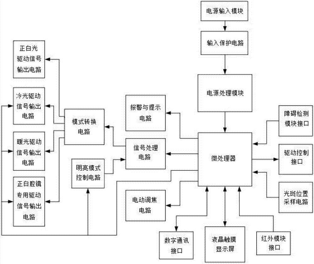
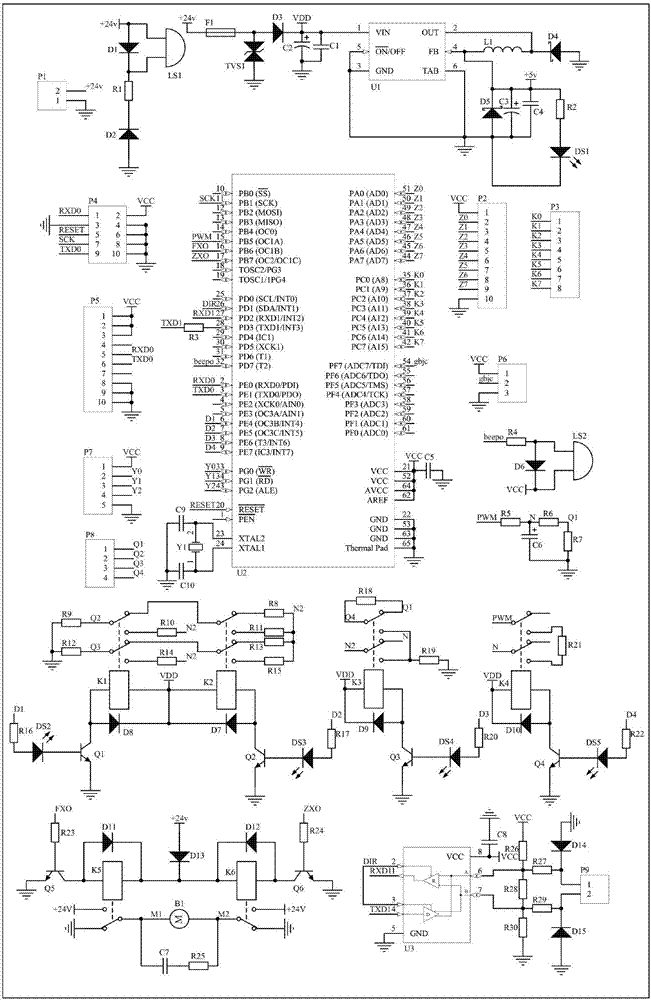
[0016] Figure 1~2 The circuit control system for digital LED shadowless lamps in operating rooms shown includes a microprocessor, a mode conversion circuit, and a communication control circuit; the upper end of the microprocessor is provided with a power processing module, and the other end of the power processing module is connected to the power supply through the input protection circuit. The input modules are connected; the input protection circuit is used to provide overvoltage protection and reverse connection protection; the lower end of the microprocessor is provided with a communication control circuit for connecting to external communication equipment;

[0017] The communication control circuit is composed of a digital communication interface, a liquid crystal touch screen and an infrared module interface, which can realize ...


PUM


Abstract

The invention discloses a circuit control system for an LED shadowless lamp of a digital operating room. The circuit control system comprises a microprocessor, a mode conversion circuit and a communication control circuit, wherein a power processing module is arranged at an input end of the microprocessor and a signal processing circuit is arranged at an output end; the other end of the signal processing circuit is connected with an LED drive signal output circuit through the mode conversion circuit; the LED drive signal output circuit is branched into a pure white light LED drive signal output circuit, a cold light LED drive signal output circuit, a warm light LED drive signal output circuit and a special LED drive signal output circuit for a pure white endoscope; an obstacle detection module interface and a light spot position sampling circuit are also arranged at the input end of the microprocessor; and a drive control interface and an electric focusing circuit are arranged at the output end of the microprocessor. The circuit control system has three communication modes and five working modes, stepless dimming or light adjustment of any gear can be achieved under the five working modes and the circuit control system also has an automatic light occlusion detection function.

Description

technical field [0001] The invention relates to a circuit control system, in particular to a circuit control system for digital operating room LED shadowless lamps. Background technique [0002] In recent years, the operating room equipment of major hospitals is developing in the direction of integration, intelligence and digitization. However, due to the independence of its control, the traditional LED surgical shadowless lamp can only be controlled and operated on the control panel, and cannot realize integrated and intelligent management control and maintenance. In addition, the existing LED surgical shadowless lamp also has the following defects: 1) Generally, the size of the shadowless light spot is manually adjusted through the disinfection handle, which cannot realize intelligent control and is not convenient to operate; even if there is an electric focusing method, it is also based on artificial The control of the jog button cannot achieve accurate digital adjustmen...

Claims


Application Information

Patent Timeline
Patent Type & Authority Applications(China)
IPC IPC(8): H05B33/08H05B44/00
CPCH05B45/00Y02B20/30
Inventor 孙晓胜汪红志
Owner NANTONG MEDICAL DEVICES
Why Eureka
Try Eureka