Cooling air duct structure of IH electrical pressure cooker

A technology of cooling air duct and electric pressure cooker, applied in pressure cooker and other directions, can solve the problems of high production cost, reduced soup, affecting the taste of cooked food, etc., and achieves the effect of good heat dissipation effect and simple structure

Inactive Publication Date: 2018-05-01
PHILIPS (JIAXING) HEALTH AND TECHNOLOGY CO LTD
View PDF11 Cites 61 Cited by
  • Summary
  • Abstract
  • Description
  • Claims
  • Application Information

AI Technical Summary

Problems solved by technology

However, not all foods can be opened immediately after cooking in an electric pressure cooker to release the pressure. , due to the high pressure in the pot, the pressure limiting valve cannot be opened immediately for deflation
If you immediately open the pressure limiting valve to release the air when the cooking is just finished, the liquid in the pot will be sprayed out from the vent hole to the outside of the pot body along with the continuous exhaust, resulting in The reduction of soup will affect the sanitation of the kitchen at least, and harm the personal safety of users at the most
The advantage of the electric pressure cooker is the functions of soup and porridge. The heating time is shortened through the fully sealed heating method, but it has to wait for a long cooling process. How to overcome this problem allows users to quickly cook after cooking. Relieve the pressure and open the lid to enjoy the food. At present, almost no one has proposed a more reasonable solution
[0003] For example, the Chines

Method used


Image

  • Cooling air duct structure of IH electrical pressure cooker
  • Cooling air duct structure of IH electrical pressure cooker
  • Cooling air duct structure of IH electrical pressure cooker

Examples


Embodiment Construction

[0020] The present invention will be further elaborated below in conjunction with the accompanying drawings and specific embodiments. These examples should be understood as only for illustrating the present invention but not for limiting the protection scope of the present invention. After reading the contents of the present invention, those skilled in the art can make various changes or modifications to the present invention, and these equivalent changes and modifications also fall within the scope defined by the claims of the present invention.

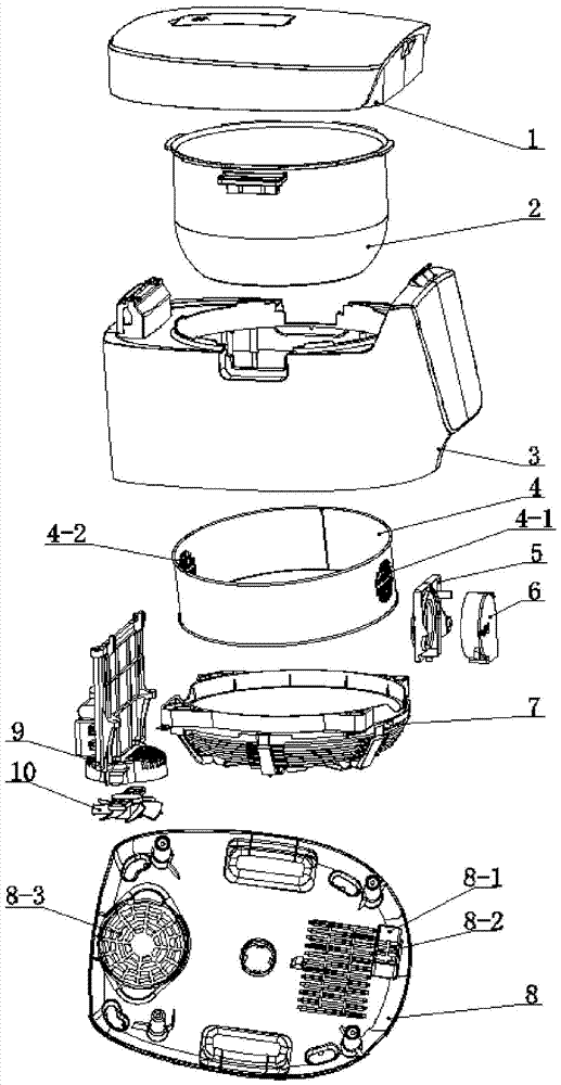
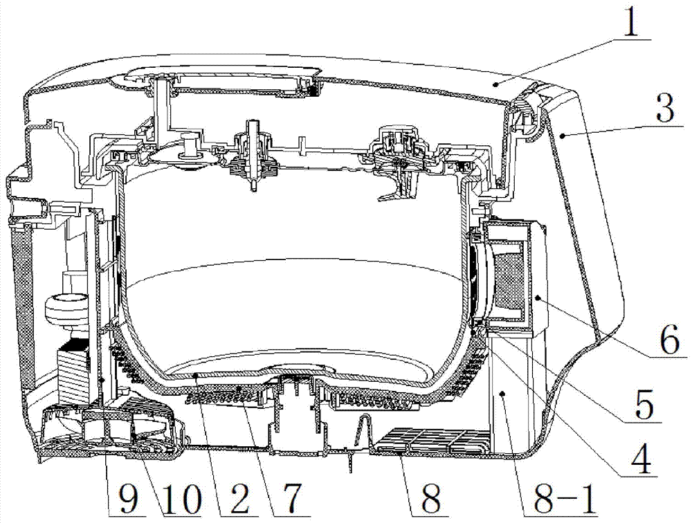
[0021] Such as Figure 1-2 As shown, in an IH electric pressure cooker with a cooling air duct structure provided by the embodiment of the present invention, it includes a lid 1 of the electric pressure cooker, an inner pot 2, a pot body 3, a bracket 4 supporting the inner pot, and an air duct opening Seal bracket 5, first fan 6, coil disk 7, base 8, third air duct section 8-1 on the base, outer air inlet 8-3, outer air outlet 8-2;...


PUM


Abstract

The invention discloses a cooling air duct structure of an IH electrical pressure cooker. The electrical pressure cooker includes a cooker body, an inner pot, a base, and an inner pot support 4; an inner air inlet and an inner air outlet are formed in a side wall of the support 4; and an outer air inlet and an outer air outlet are formed in the base. The cooling air duct structure includes: a first cooling air duct section arranged in a side wall of the cooker body, wherein a lower end of the first cooling air duct section communicates with the outer air inlet, and an upper end of the first cooling air duct section communicates with the inner air inlet; a second cooling air duct section formed by a gap between an outer surface of the inner pot and an inner surface of the inner pot support4, wherein cooling air flowing into the second cooling air duct section from the inner air inlet can flow out of the inner air outlet; and a first fan, wherein the first fan is arranged outside the inner air outlet and can pump the cooling air in the second cooling air duct section out of the electric pressure cooker via the outer air outlet. The cooling air duct structure is simple in structure;after a user uses the electrical pressure cooker to cook soup and congee, the user can open the cooker instantly and eat the food.

Description

technical field [0001] The invention relates to an internal structure of an IH (Induction Heating, electromagnetic induction heating) electric pressure cooker, in particular to a cooling air passage structure inside the IH electric pressure cooker. Background technique [0002] At present, electric pressure cookers are generally equipped with a pressure limiting valve, and its function is to enable the user to realize the purpose of releasing air and pressure by operating the pressure limiting valve after cooking. However, not all foods can be opened immediately after cooking in an electric pressure cooker to release the pressure. , due to the higher pressure in the pot, the pressure limiting valve cannot be opened immediately for deflation. If you immediately open the pressure limiting valve to release the air when the cooking is just finished, the liquid in the pot will be sprayed out from the vent hole to the outside of the pot body along with the continuous exhaust, res...

Claims


Application Information

Patent Timeline
IPC IPC(8): A47J27/09
CPCA47J27/09
Inventor 陈建军谢先福
Owner PHILIPS (JIAXING) HEALTH AND TECHNOLOGY CO LTD
Why Eureka
Try Eureka