Method for metallurgically bonding a cylinder liner into a bore in an engine block

An engine block, metallurgical combination technology, applied in the direction of engine components, machines/engines, cylinders, etc., can solve problems such as growth, achieve the effect of reducing weight, improving durability and performance, and reducing hole deformation

Inactive Publication Date: 2018-05-01
GM GLOBAL TECH OPERATIONS LLC
View PDF7 Cites 2 Cited by
  • Summary
  • Abstract
  • Description
  • Claims
  • Application Information

AI Technical Summary

Problems solved by technology

Additionally, during operation at elevated temperatures, gaps may form and / or grow between the liner and cylinder

Method used


Image

  • Method for metallurgically bonding a cylinder liner into a bore in an engine block
  • Method for metallurgically bonding a cylinder liner into a bore in an engine block
  • Method for metallurgically bonding a cylinder liner into a bore in an engine block

Examples


Embodiment Construction

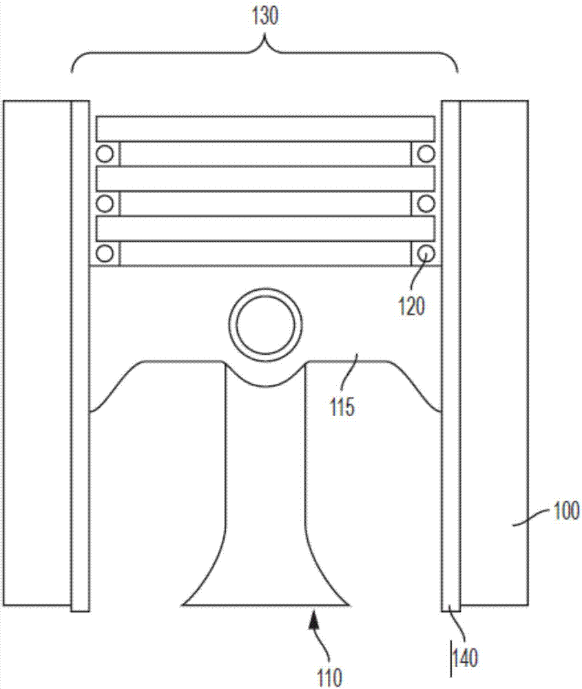
[0038] refer to figure 1 , the piston 110 is positioned within the cylinder bore 130 of the engine block 100 . Piston 110 includes a head 115 having one or more piston rings 120 . The cylinder liner 140 is installed in the cylinder bore 130 . During a combustion cycle of an internal combustion engine (ICE), an air / fuel mixture is provided to cylinders of the ICE (eg, cylinder 130 ). The air / fuel mixture is compressed and / or ignited and combusted to provide output torque via a piston (eg, piston 10 ) located within the cylinder. During operation of the ICE, cylinder liner 140 may be in contact with one or more rings 120 and / or piston 110 . Cylinder liner 140 may serve to prevent wear or degradation of engine block 100 from contact with piston 110 and / or one or more fuels and combustion gases. The engine block side profile on the exterior of cylinder liner 140 may substantially conform to the internal profile of cylinder 130 .

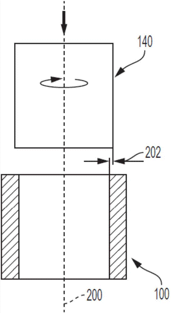
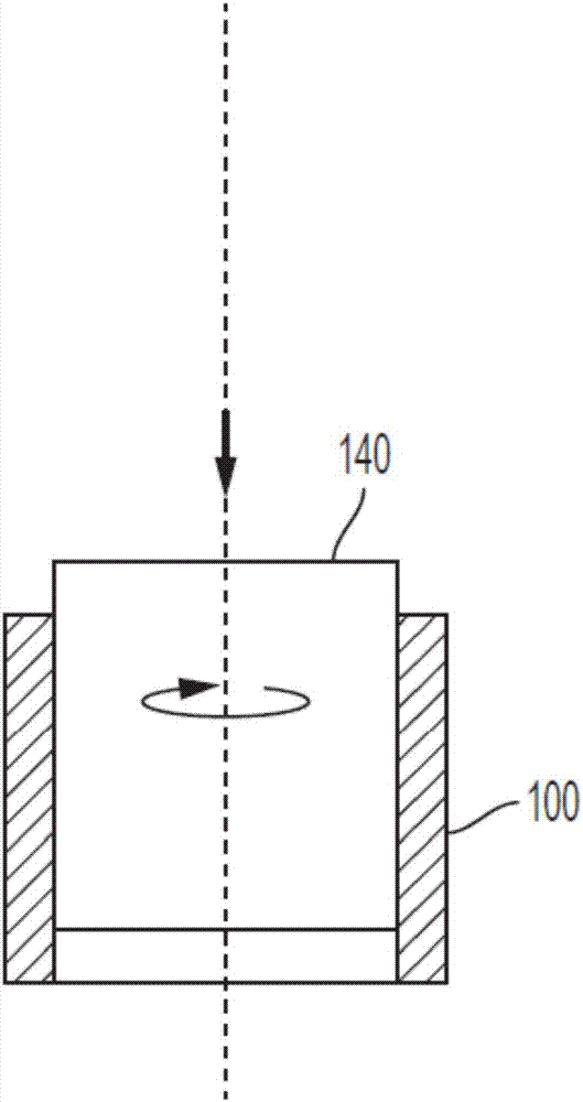
[0039] In an exemplary embodiment, cylinder l...


PUM


Abstract

A method for metallurgically bonding a cylinder liner in a bore in an engine block includes axially aligning the cylinder liner with a bore in the engine block, rotating the cylinder liner about the aligned axis, and translating the cylinder liner along the aligned axis to position the cylinder liner within the bore.

Description

technical field [0001] The present disclosure relates to a method for metallurgically bonding a cylinder liner into a bore in an engine block. Background technique [0002] This introduction generally presents the context of the disclosure. To the extent that the work of the named inventors described in the introduction and in various aspects of this specification is not an indication that it was prior art at the time of filing this application, it has never been admitted, either expressly or impliedly, as prior art to this application. technology [0003] During a combustion cycle of an internal combustion engine (ICE), an air / fuel mixture is provided to cylinders within the engine block of the ICE. The air / fuel mixture is compressed and / or ignited and combusted to provide output torque through pistons located within the cylinders. As the piston moves within the cylinder, friction between the piston and cylinder and the presence of fuel wears and degrades the cylinder su...

Claims


Application Information

Patent Timeline
Patent Type & Authority Applications(China)
IPC IPC(8): B23K20/12
CPCB23K20/129B23K2101/006F02F1/004F02F2200/00B23K31/02B23K37/053
Inventor Q·王W·L·米勒J·杨H·李
Owner GM GLOBAL TECH OPERATIONS LLC
Why Eureka
Try Eureka