Main system device pre-introduction method

A main system and equipment technology, applied in construction, building construction, etc., can solve the problems of delayed dome hoisting, unavailability of special tools, and long introduction of main system equipment, etc., to optimize the construction process, shorten the project cycle, optimize The effect of the total duration

Active Publication Date: 2019-11-01
宋丰伟
View PDF1 Cites 0 Cited by
  • Summary
  • Abstract
  • Description
  • Claims
  • Application Information

AI Technical Summary

Problems solved by technology

However, for primary system equipment with large weight, large volume, high installation technical requirements, and on the main key path of the project, the shortcomings of the existing technology are: after the main body of the internal structure is completed, it is necessary to wait for the dome hoisting welding and ring hoisting It can only be introduced after debugging is available, and this process takes about 5 months
[0016] (2) Unless the design is greatly changed, the introduction of the main equipment before capping will have a greater safety risk
[0017] The plant structure and special tools are considered according to the horizontal introduction of the main system equipment from the equipment gate. If the introduction method is changed, it is difficult to control the horizontal position and accuracy, and there is a greater safety risk;
[0018] (3) The introduction of main equipment before capping will seriously affect the hoisting of the dome
[0019] If the main equipment, especially the pressure vessel, is introduced before the capping, it will take a long time to construct the reactor cavity pool to create a clean environment, and because some special tools are not available, the introduction of the main system equipment will take a long time, resulting in a serious delay in the dome hoisting;
[0020] (4) The ring crane must complete the commissioning and load test after capping
However, the object of this patent document is only the equipment on the non-critical path such as the factory building, and cannot solve the problem of introducing the main system equipment of the primary circuit

Method used


Image

  • Main system device pre-introduction method

Examples


Embodiment Construction

[0090] The present invention will be described in detail below in conjunction with specific embodiments. The following examples will help those skilled in the art to further understand the present invention, but do not limit the present invention in any form. It should be noted that those skilled in the art can make several changes and improvements without departing from the concept of the present invention. These all belong to the protection scope of the present invention.

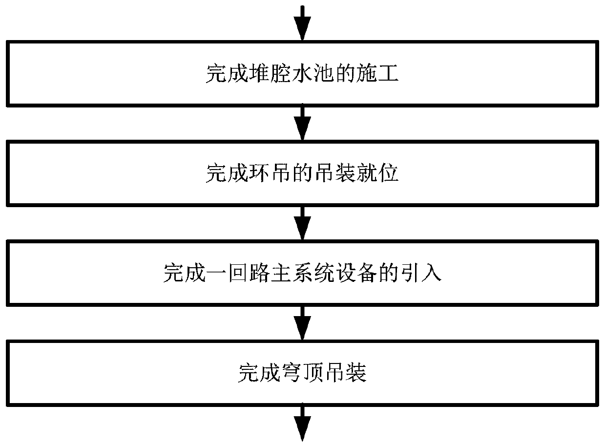
[0091] The invention relates to a method for installing primary system equipment of a nuclear power plant, in particular to a pre-introduction construction method for quickly completing the installation of main system equipment in place before the reactor building is capped.

[0092] One of the characteristics is to make the cladding module of the pile cavity pool, which is hoisted into the pile cavity before the construction of the pile cavity pool wall, and used as a formwork for the concrete construct...


PUM


Abstract

The invention provides a main system equipment pre-introduction method. The main system equipment pre-introduction method is characterized in that first, a reactor cavity water tank blanket module isproduced and is lifted inside the reactor cavity position before construction of a wall body of a reactor cavity water tank as a template for the concrete construction of the wall body; after the wallbody is completed, support plates and support frames in the module are removed, so that an introduction environment for a pressure vessel is possessed; second, modular assembly of a ring crane tracksupporting beam and a ring crane crossbeam is completed on the ground, and entire hoisting in position and adjustment for fitting the position are completed before main system equipment is pre-introduced; and third, all or part of the main system equipment is turned over to be erected on the outside ground of a workshop by heavy-duty cranes and then vertically hoisted in position from the top of areactor building. Through parallel operation of a plurality of overturned sites, multiple sets of construction machinery and personnel cooperate with each other, a method of quickly adjusting the position and level degree of the equipment is adopted, and thus the flow process of a plurality of main system equipment being turned over to be erected and hoisted in position is realized.

Description

technical field [0001] The invention relates to a method for installing large-scale equipment, in particular to a method for pre-introducing main system equipment. In particular, it relates to a construction method for pre-introduction and installation of primary circuit main system equipment in non-AP series pressurized water reactor nuclear power plants. Background technique [0002] At present, most reactor-type PWR nuclear power plants have the following design features in their nuclear island plant design: [0003] (1) The main structure of the reactor building is reinforced concrete; [0004] (2) The containment has prestressing requirements; [0005] (3) Steel-lined cladding for structures with tightness requirements, such as reactor cavity pools, refueling pools, containment shells, etc.; [0006] (4) Horizontal equipment lead-in passages, including facilities such as gantry frames, heavy-duty trolleys, tracks, and equipment gates, are designed to meet the lead-in...

Claims


Application Information

Patent Timeline
Patent Type & Authority Patents(China)
IPC IPC(8): E04B1/35
CPCE04B1/35
Inventor 宋丰伟
Owner 宋丰伟
Why Eureka
Try Eureka