Side draught type extractor hood

A range hood and side-suction technology, applied in the field of side-suction range hoods, can solve the problems of affecting the operating efficiency and service life of the push rod, reducing the service life of the push rod, increasing friction, etc., so as to avoid the smoke baffle Pause and jitter, prolong service life, improve the effect of using conditions

Pending Publication Date: 2018-05-01
NINGBO FOTILE KITCHEN WARE CO LTD
View PDF4 Cites 1 Cited by
  • Summary
  • Abstract
  • Description
  • Claims
  • Application Information

AI Technical Summary

Problems solved by technology

The above-mentioned installation method has the following disadvantages: 1. The range hood has been in the oil fume environment for a long time, and the common shaft and hole are connected. Use will reduce the service life of the push rod; 2. The gap between the shaft and the hole will cause the stop and shake when the smoke baffle is opened and closed due to the gap when the smoke baffle is moving and the direction of the smoke baffle is changed due to the force. Phenomenon; 3. The range hood box is made of sheet metal, and its assembly proce

Method used


Image

  • Side draught type extractor hood
  • Side draught type extractor hood
  • Side draught type extractor hood

Examples


Embodiment 1

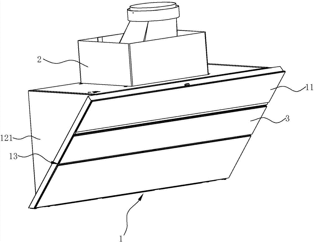
[0032] see figure 1 and figure 2 , a side suction range hood with an electric push rod mechanism, including a casing 1, a fan cover 2 and a fan system (not shown), the casing 1 is installed under the fan cover 2, and the fan system is installed under the fan cover 2 Inside and partly located on the back side of the casing 1.

[0033] The casing 1 includes a front panel 11 and a left side panel 121 and a right side panel 122 on both sides. The panel 11 is provided with an air inlet 13, and the smoke baffle 3 adapted to the size and shape of the air inlet 13 is hinged on the inlet. There are 13 outlets. When the range hood is turned on, the smoke baffle 3 is opened, and the fan system sucks the air in the casing 1 and discharges it to the public flue or outdoors through the fan cover 2, and a negative pressure is formed in the casing 1 so that the airflow entrained with oil fumes flows from the inlet The tuyere 13 enters the casing 1, and is then discharged to the public fl...

Embodiment 2

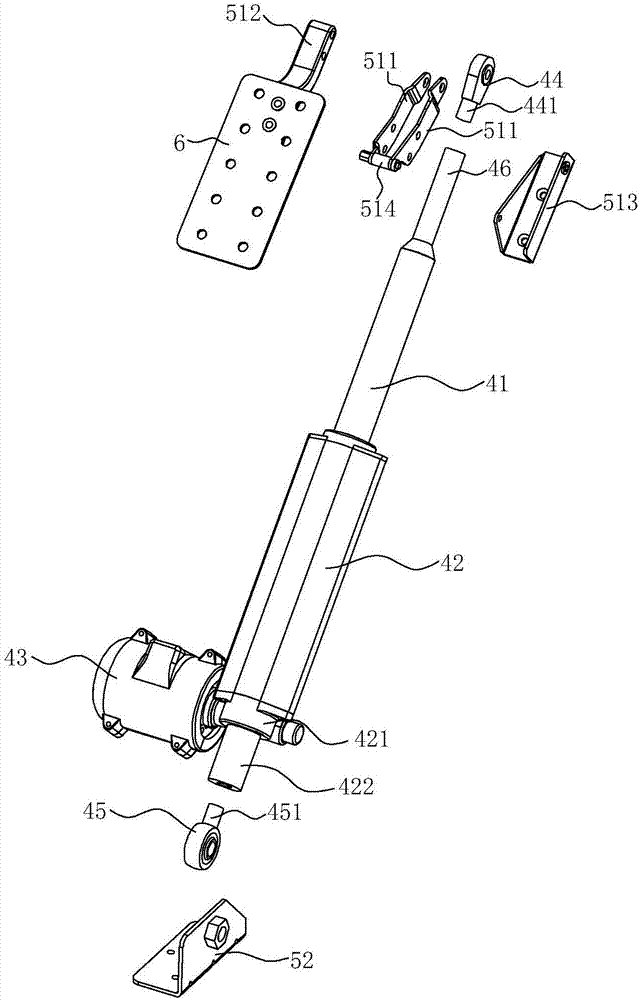
[0043] see Figure 4 with Figure 5 , In this embodiment, the difference from the first embodiment above is that the first bearing 44 is a rod end bearing, and the second bearing 45 is a bearing with a seat. The end cover 421 is provided with a shaft hole 423 , the second bearing 45 is connected with the end cover 421 through the shaft hole 423 , and the base 451 of the second bearing 45 is used for connecting with the casing 1 .

[0044] Similarly, the electric push rod mechanism 4 with double bearing structure can effectively reduce the gap error and avoid the stoppage and vibration of the smoke baffle 3 caused by the gap when the smoke baffle 3 changes direction under force when the smoke baffle 3 is moving. Phenomenon.

Embodiment 3

[0046] see Image 6 with Figure 7 , In this embodiment, the difference from the second embodiment above is that the first bearing 44 is a rod end joint bearing, and the second bearing 45 is a bearing with a seat.

[0047] The above-mentioned electric push rod mechanism 4 with double bearing structure enables the rotation of the smoke baffle 3 to be realized through bearings, which has the following advantages:

[0048] 1. The bearing has high precision and small gap, which can effectively reduce the gap error and avoid the pause and vibration of the smoke baffle 3 caused by the gap when the smoke baffle 3 is forced to change direction when the smoke baffle 3 is moving.

[0049] 2. The rod end joint bearing can rotate according to the bearing center, and has the characteristics of compensating the installation error when the push rod 41 and the push rod housing 42 are assembled. When the centers of the first bearing 44 and the second bearing 45 are slightly offset, it can pas...


PUM


Abstract

The invention discloses a side draught type extractor hood. The side draught type extractor hood includes a machine shell. The right front of the machine shell is provided with an air inlet. A smoke deflector is arranged in the air inlet. The machine shell is internally provided with an electric pushing rod mechanism used for driving the smoke deflector to overturn. The electric pushing rod mechanism includes a pushing rod outer shell and a pushing rod carrying out linear reciprocating motion relative to the pushing rod outer shell. The side draught type extractor hood is characterized in thatthe end, away from the pushing rod outer shell, of the pushing rod is connected with the smoke deflector through a first bearing. The end, away from the pushing rod, of the pushing rod outer shell isconnected with the machine shell through a second bearing. Through arranging the electric pushing rod mechanism into a double-bearing structure, the pushing rod can rotate around the bearing center,the pushing rod can be inclined to compensate disadvantages of low accuracy, when the centers of a rod end knuckle bearing and a mounted bearing are in misregistration, the straightness accuracy of the pushing rod can be ensured through a rotation shaft of the rod end knuckle bearing, and the radial force inside when the pushing rod moves can be eliminated.

Description

technical field [0001] The invention relates to the field of range hoods, in particular to a side suction type range hood with an electric push rod mechanism. Background technique [0002] Existing side suction range hoods usually include a casing, a fan system arranged in the casing, and a control switch. The casing includes side panels on both sides and a panel on the side facing the stove. The panel is provided with a suction port. After the power supply of the fan system is turned on, the oil fume is sucked into the fan system by the suction port and discharged to the public flue. This range hood is inconvenient to clean. In addition to cleaning the shell, it is also necessary to extend into the air suction port to clean the fan blades of the fan system in the shell or the partition net positioned at the air suction port. [0003] For this reason, improvements have been made on this basis, as the Chinese patent application number 201020026644.5, which discloses a range ...

Claims


Application Information

Patent Timeline
IPC IPC(8): F24C15/20
CPCF24C15/2092
Inventor 余旭锋田涛郑幸李斌茅忠群诸永定
Owner NINGBO FOTILE KITCHEN WARE CO LTD
Why Eureka
Try Eureka