Sleeve type soil grasping device sensor device for measuring test soil body inside micro deformation in geotechnique direct shearing test
A technology of grabbing device and soil body, applied in the field of geotechnical, can solve the problems of inability to accurately represent the deformation of soil body, large size of shear box, etc., and achieve the effects of avoiding errors, improving measurement accuracy, and improving accuracy.
- Summary
- Abstract
- Description
- Claims
- Application Information
AI Technical Summary
Problems solved by technology
Method used
Image
Examples
Embodiment 1
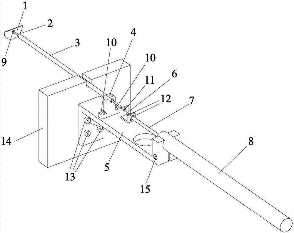
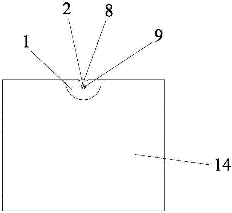
[0026]Embodiment 1: This embodiment is a sleeve-type soil grab device used alone. Its structure is shown in Figure 1-Figure 8. It consists of a spoon-shaped soil grab 1, a displacement transmission rod 2, a displacement transmission rod sleeve 3, and a sleeve Bracket 4, fixed bracket 5, displacement transmission adapter 6, displacement sensor 8 (including displacement sensor telescopic rod 7), and fixing nuts, screws and other components, wherein the fixing nuts and screws include: gripper fixing screws Cap 9, sleeve bracket fixing screw 10, displacement transmission rod fixing nut 11, displacement sensor telescopic rod fixing nut 12, fixing bracket fixing screw 13, displacement sensor clamping screw 15. Among them: the spoon-shaped soil grabber 1 is a semicircular sheet-shaped rigid component, and a hole is prefabricated on it for passing through the displacement transmission rod 2. The inner diameter of the hole on the soil grabber 1 is the same as the outer diameter of the d...
Embodiment 2
[0028] Embodiment 2: This embodiment is the case where three sleeve-type soil grab devices are used in parallel, as shown in Figure 9. The specific implementation steps are: in the sample filling stage before the geotechnical direct shear test is carried out, three The spoon-shaped soil grabber 1 is embedded in the corresponding design position in the test soil in the shear box, and the three spoon-shaped soil grabbers 1 are clamped and fixed on one end of three displacement transmission rods 2 of different lengths with the soil grabber fixing nut 9. The specific lengths of the three displacement transmission rods 2 are designed according to the needs of the experiment; the three displacement transmission rods 2 are passed through three displacement transmission rod sleeves 3 of corresponding lengths, and the three displacement transmission sleeves 3 are passed through three sleeve brackets 4, respectively. Two sleeve bracket fixing screws 10 fix the three sleeve brackets 4 on ...
PUM
 Abstract
Description
Claims
Application Information
 - R&D
- Intellectual Property
- Life Sciences
- Materials
- Tech Scout
- Unparalleled Data Quality
- Higher Quality Content
- 60% Fewer Hallucinations
Browse by: Latest US Patents, China's latest patents, Technical Efficacy Thesaurus, Application Domain, Technology Topic, Popular Technical Reports.
© 2025 PatSnap. All rights reserved.Legal|Privacy policy|Modern Slavery Act Transparency Statement|Sitemap|About US| Contact US: help@patsnap.com


