A reactor core melt capture device

A reactor and melting technology, which is applied in the field of nuclear safety, can solve the problems of not considering the grouping of core melts for trapping and cooling, and achieves the effects of reliable cooling method, reduced radiation dose, and improved decay heat export power

Active Publication Date: 2021-06-25
CHINA NUCLEAR POWER ENG CO LTD
View PDF28 Cites 0 Cited by
  • Summary
  • Abstract
  • Description
  • Claims
  • Application Information

AI Technical Summary

Problems solved by technology

[0008] However, none of the above-mentioned patents related to the core catcher considers the use of independent containers to collect and cool the core melt in groups.

Method used


Image

  • A reactor core melt capture device

Examples


Embodiment Construction

[0035] The specific implementation manners of the present invention will be further described below in conjunction with the accompanying drawings.

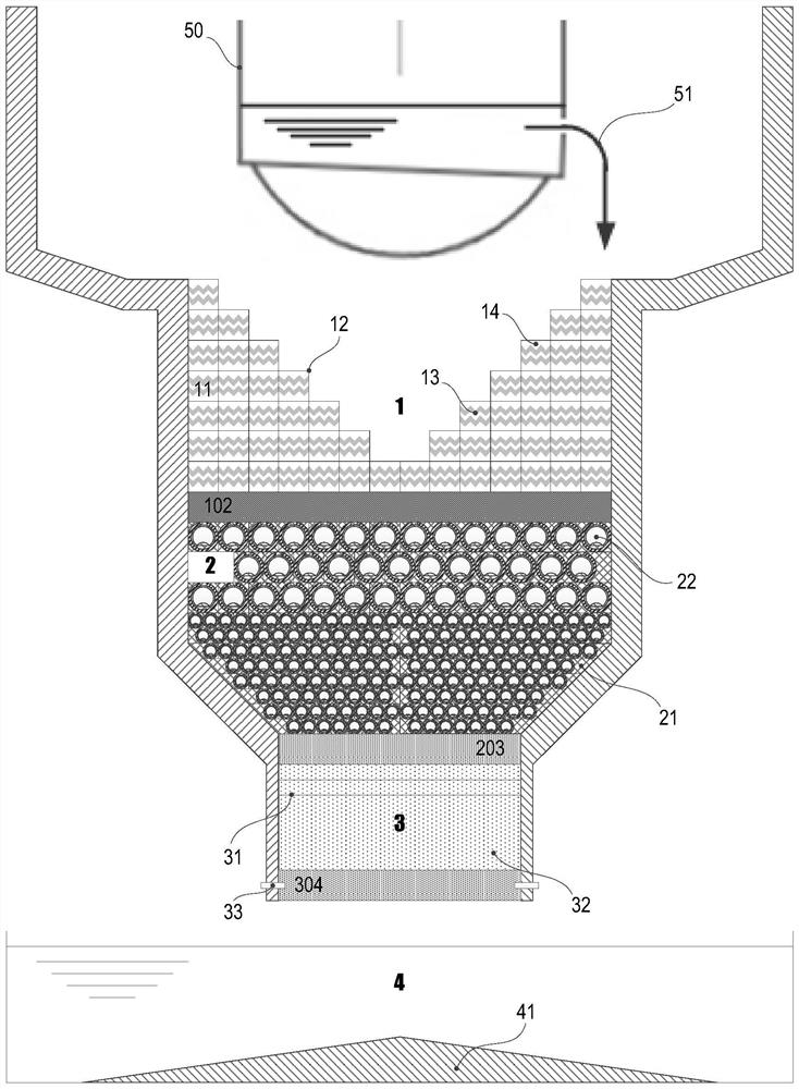
[0036] The structure of the exemplary reactor core melt capture device of the present invention is as follows figure 1 As shown, it includes an early melt retention chamber 1, a melt group retention chamber 2, a retention container transfer channel 3, a cooling water pool 4, a sacrificial material box 11, a box body 12, a partition in the box 13, and a sacrificial material in the box 14 , sacrificial material filler 21, melt retention container 22, channel partition 31, melt adsorption particles 32, fuse device 33, conical spreading surface 41, primary isolation plate 102, secondary isolation plate 203, final barrier plate 304 .

[0037] The early melt retention chamber 1 , the melt group retention chamber 2 , the retention vessel transfer channel 3 , and the cooling water pool 4 are sequentially arranged below the reactor pressu...


PUM


Abstract

The invention belongs to the technical field of nuclear safety, and relates to a reactor core molten matter collection device. The trapping device includes an early melt retention chamber, a melt group retention chamber, a transfer channel for the retention vessel, a cooling water pool arranged in sequence below the reactor pressure vessel, and a device arranged in the early melt retention chamber. There is a sacrificial material box with sacrificial material, the molten material retention container and sacrificial material filling filled in the molten material grouping retention chamber, the molten material adsorption particles filled in the transfer channel of the retention container, wherein the The melt retention container is a hollow shell with an opening. By using the reactor core melt collection device of the invention, the reactor core melt can be collected and cooled in groups by independent packaging containers under serious accident conditions.

Description

technical field [0001] The invention belongs to the technical field of nuclear safety, and relates to a reactor core molten matter collection device. Background technique [0002] After the serious accidents at the Three Mile Island and Chernobyl nuclear power plants, the nuclear power industry began to focus on research and research on the prevention and mitigation of severe accidents. Due to engineering and other requirements. [0003] When a serious accident occurs in a pressurized water reactor nuclear power plant, the loss of core waste heat removal means will evaporate and exhaust the coolant, the core will be exposed and continue to heat up, the fuel elements will melt due to the loss of cooling, and the core melt will fall into the pressure vessel ( RPV) lower chamber, which in turn causes the failure of the lower head of the pressure vessel. If effective measures cannot be taken to cool it, the core melt may melt through the pressure vessel. After the pressure ve...

Claims


Application Information

Patent Timeline
Patent Type & Authority Patents(China)
IPC IPC(8): G21C9/016G21C15/18
CPCG21C9/016G21C15/18Y02E30/30
Inventor 韩旭邢继朱晨王一光元一单刘卓
Owner CHINA NUCLEAR POWER ENG CO LTD
Why Eureka
Try Eureka