Motor assembly machine capable of continuously automatically loading single rotating shafts

An automatic feeding and motor unit technology, applied in the manufacture of motor generators, electromechanical devices, electric components, etc., can solve the problems of high motor shaft discharge cost, inability to continuously put in, low efficiency, etc., and achieve simple structure, Easy to operate and ensure the effect of stability

Active Publication Date: 2018-05-01
深圳市赛金科技有限公司
View PDF4 Cites 4 Cited by
  • Summary
  • Abstract
  • Description
  • Claims
  • Application Information

AI Technical Summary

Problems solved by technology

[0003] Most of the existing motor shafts are pressed in by using a fixed carrier that cooperates with the motor casing, and then the motor shaft is pushed in through the motor shaft jacking device on the side. Most of the motor shafts are inserted manually or by a robot. The manual operation is inefficient and cannot be placed in the motor shaft conveying trough, and the cost of discharging the motor shaft by a manipulator is high, and there will be a certain time interval at the same time, and the efficiency is also not high

Method used


Image

  • Motor assembly machine capable of continuously automatically loading single rotating shafts
  • Motor assembly machine capable of continuously automatically loading single rotating shafts
  • Motor assembly machine capable of continuously automatically loading single rotating shafts

Examples


Embodiment Construction

[0035] In order to enable those skilled in the art to better understand the technical solution of the present invention, the present invention will be described in detail below in conjunction with the accompanying drawings. The description in this part is only exemplary and explanatory, and should not have any limiting effect on the protection scope of the present invention. .

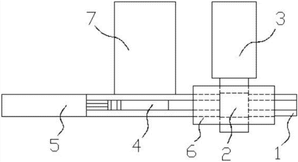
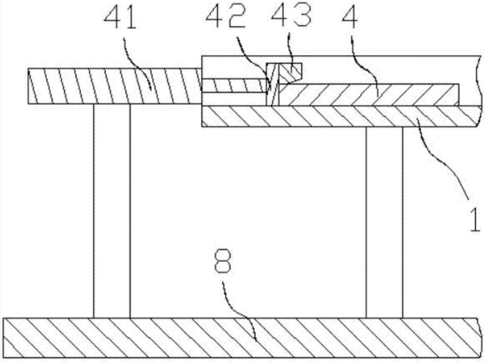
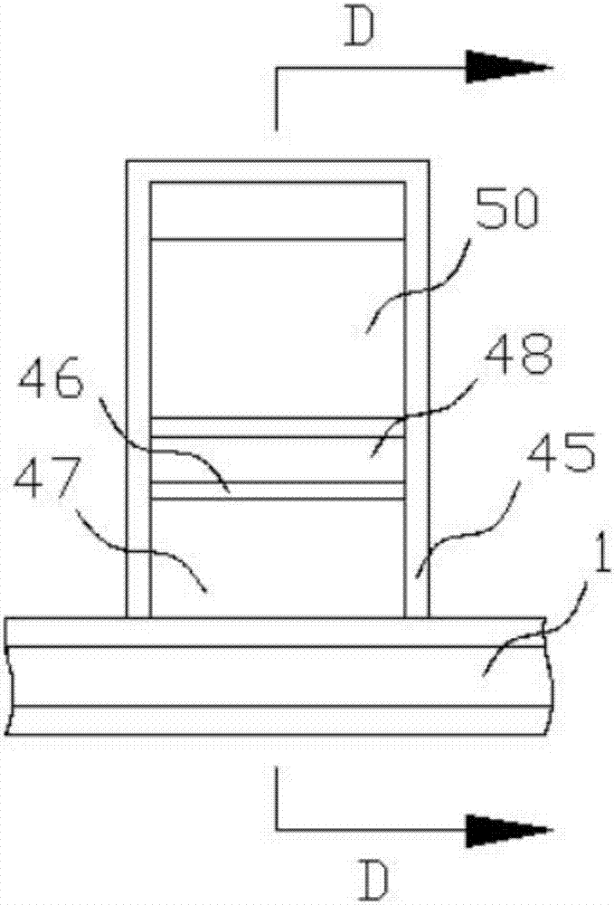
[0036] Such as Figure 1-Figure 10 As shown, the specific structure of the present invention is: a motor assembly machine for continuous and automatic feeding of a single rotating shaft, which includes a lower bracket 8 and an upper bracket 9, and the lower bracket 8 is provided with mutually matched motor housing positioning The discharge mechanism and the motor shaft conveying trough 1, the left side of the motor shaft conveying trough 1 is equipped with a jacking device 5, and the rear side is equipped with a motor shaft feeding device 7, and the motor shaft feeding device 7 includes a set The mate...


PUM


Abstract

The invention relates to a motor assembly machine capable of continuously automatically loading single rotating shafts. The motor assembly machine comprises a lower bracket, an upper bracket, a motorhousing positioning feeding mechanism, a motor shaft conveyor trough, a jacking device and a motor shaft loading device, wherein the motor shaft loading device comprises a motor shaft loading box; themotor shaft loading box is free of a cover plate or a front side plate; a motor shaft loading stop block is arranged in the motor shaft loading box; a motor shaft loading inclined plate is arranged at the front side of the motor shaft loading stop block; an L-shaped motor shaft loading lifting block is arranged at the rear side of the motor shaft loading stop block; the motor shaft loading lifting block is connected with a motor shaft loading lifting cylinder; and a motor shaft return sliding block which inclines backwards is arranged at the part, at the rear side of the motor shaft loading lifting block, of the motor shaft loading box. Single motor shafts can continuously slide into the motor shaft conveyor trough from the motor shaft loading inclined plate through coordination of the adjustable L-shaped motor shaft loading lifting block and the motor shaft loading stop block, so that the interval time is greatly shortened, and continuous single motor shaft feeding and pressing can be achieved through coordination with the jacking device.

Description

technical field [0001] The invention relates to the field of automatic processing equipment, in particular to a motor assembly machine for continuous and automatic feeding of a single rotating shaft. Background technique [0002] The motor is a commonly used power drive part with a wide range of applications. Most of them include a machined and assembled motor casing and a motor shaft passing through the motor casing. The motor casing contains components that can drive the motor shaft. Most of the process will use the press-in equipment of the motor shaft. [0003] Most of the existing motor shafts are pressed in by using a fixed carrier that cooperates with the motor shell, and then the motor shaft is pushed in through the motor shaft jacking device on the side. Most of the motor shafts are inserted manually or by a robot. In the motor shaft conveying trough, the efficiency of manual operation is low, and it cannot be put in continuously. The cost of discharging the motor ...

Claims


Application Information

Patent Timeline
Patent Type & Authority Applications(China)
IPC IPC(8): H02K15/00B23P19/00B23P19/027
CPCB23P19/001B23P19/027H02K15/00
Inventor 邓君龙剑宇白云何昆
Owner 深圳市赛金科技有限公司
Why Eureka
Try Eureka