Robot motion track planning method and related device

A technology of robot movement and movement trajectory, which is applied in the direction of instruments, non-electric variable control, two-dimensional position/channel control, etc., and can solve problems such as inability to find arcs, inability to find arc transitions, sharp corners, etc.

Active Publication Date: 2018-05-01
SHENZHEN A&E INTELLIGENT TECH INST CO LTD
View PDF8 Cites 23 Cited by
  • Summary
  • Abstract
  • Description
  • Claims
  • Application Information

AI Technical Summary

Problems solved by technology

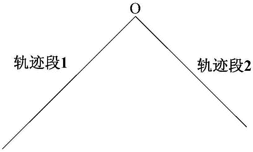
[0005] This faces another problem: still see Figure 1a , if consecutive straight line segments are not on the same straight line, there will be sharp corners
Although the vector superposition method can be used to replace sharp corners with circular arcs, it is definitely applicable only in the scene where a straight line segment is transferred from a straight l

Method used


Image

  • Robot motion track planning method and related device
  • Robot motion track planning method and related device
  • Robot motion track planning method and related device

Examples


Embodiment Construction

[0065] The technical terms, abbreviations or abbreviations that may be used in the present invention are as follows:

[0066] TCP point: tool coordinate center point;

[0067] Linear motion: the robot TCP point moves along a straight line trajectory in Cartesian space;

[0068] Circular movement: the CP point of the robot moves along a circular arc trajectory in Cartesian space;

[0069] CP: continuous motion, trajectory motion in Cartesian space, including linear motion and circular motion;

[0070] Bezier curve of degree n: The formula of Bezier curve of degree n is: are called Bernstein basis functions, t=0 corresponds to the start point of the Beizer curve, and t=1 corresponds to the end point of the Beizer curve.

[0071] P 0 -P n These n feature points or control points define n-degree Bezier curves in the plane or in three-dimensional space, and the polygons formed by them are called feature polygons or control polygons. Among them, P 0 as the starting point, ...


PUM


Abstract

The scheme relates to the field of motion control and especially relates to the robot motion track planning technology. In a robot motion track planning method, feature points of a degree n cubic Bezier curve are determined according to a first CP motion track section and a second CP motion track section, and n is not less than 4 (401); the degree n cubic Bezier curve is constructed according to the above feature points and serves as a smooth transition track section between the first CP motion track section and the second CP motion track section (402). The degree n cubic Bezier curve is adopted to serve as the smooth transition track section between the two CP motion track sections, the smooth transition track section is tangent to the first CP motion track section at an initial point ofthe smooth transition track section with the same curvature, the smooth transition track section is tangent to the second CP motion track section at a termination point of the smooth transition tracksection with the same curvature, so that serial CP motion smooth transition can be realized, in addition, the speed has no need to be reduce to 0, and the acceleration does not jump.

Description

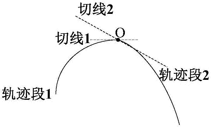
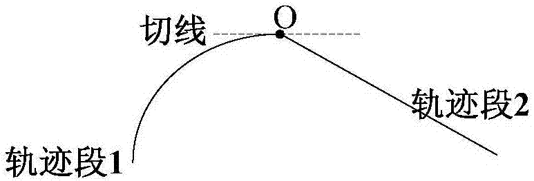
technical field [0001] The invention relates to the field of motion control, and more specifically, relates to robot motion trajectory planning technology. Background technique [0002] In the motion control of the robot, the trajectory motion of the controlled part (such as the manipulator) can be divided into CP motion (continuous operation, including linear motion and arc motion) and PTP motion (point-to-point motion). [0003] When planning the motion trajectory of the robot, it may be necessary to perform multiple CP motions continuously. Take two consecutive CP movements as an example, please refer to Figure 1a , CP motion trajectory segment 1 (also referred to as trajectory segment 1) and CP motion trajectory segment 2 (also referred to as trajectory segment 2) can be straight line segments respectively, in addition, circular arc segments and circular arc segments ( Figure 1b ), arc segment and straight line segment ( Figure 1c with Figure 1d ) continuously. ...

Claims


Application Information

Patent Timeline
IPC IPC(8): G05D1/02
CPCG05D1/0212G05D1/00G05D1/02
Inventor 张志明
Owner SHENZHEN A&E INTELLIGENT TECH INST CO LTD
Why Eureka
Try Eureka