Forcing mixer

A technology of forced mixing and mixing ring, which is applied in the direction of mixers, mixing methods, chemical instruments and methods, etc., to achieve the effects of avoiding frictional heating, improving fluid delivery flow, and reducing resistance along the way

Active Publication Date: 2018-05-04
大庆诺思环保科技有限公司
View PDF6 Cites 0 Cited by
  • Summary
  • Abstract
  • Description
  • Claims
  • Application Information

AI Technical Summary

Problems solved by technology

This delay is impractical for many chemical analyses.

Method used


Image

  • Forcing mixer
  • Forcing mixer
  • Forcing mixer

Examples


Embodiment Construction

[0019] The present invention will be further described below in conjunction with accompanying drawing:

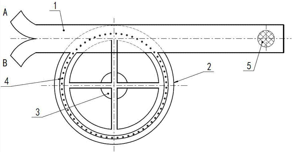
[0020] An embodiment of the forced mixer of the present invention, such as figure 1 As shown, it includes a mixing pipeline 1, a particle driving disk 2, a rotating motor 3 and a particle recovery disk 5; the front end of the mixing pipeline 1 is provided with a first inlet A and a second inlet B, which are respectively used to connect two kinds of particles to be mixed. liquid;

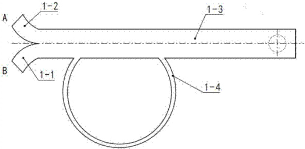
[0021] Such as Figure 2~3 As shown, a mixing ring 1-4 is provided on the abdomen of the mixing pipe 1, and the projection of the mixing ring 1-4 is an arc structure, and the two ports of the mixing ring 1-4 are misplaced with the mixing pipe. 1 is connected, and disturbing particles 4 are installed in the mixing ring 1-4; the particle driving disc 2 is located below the mixing ring 1-4 and placed concentrically with the mixing ring 1-4;

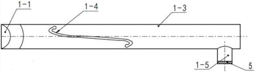
[0022] Such as Figure 4~5 As shown, the particle driv...


PUM


Abstract

The invention discloses a forcing mixer. The forcing mixer comprises a mixed pipeline, a particle driving disc, a rotary motor and a particle recycling disc, wherein a first inlet and a second inlet are formed at the front end of the mixing pipeline and are respectively used for connecting two liquid to be mixed; a mixing ring is arranged on an abdominal part of the mixing pipeline; projection ofthe mixing ring is a circular arc structure; two ports of the mixing ring are staggered and are connected with the mixing pipeline; disturbance particles are put in the mixing ring; the particle driving disc is positioned under the mixing ring and is concentric to the mixing ring; the particle driving disc comprises an insulated support and a circular orbit fixed to the insulated support; positively charged particles are put on the circular orbit at intervals; the insulated support of the particle driving disc is driven by the rotary motor to rotate; a cylindrical particle collection hole is formed in the tail part of a straight pipe of the mixing pipeline; a particle recycling disc is mounted at the particle collection hole. The forcing mixer is mainly applied to mixing of different substances in channels with small sizes, and has the characteristics of simple structure, high mixing efficiency, small on-way resistance and the like.

Description

technical field [0001] The invention relates to the field of liquid flow, in particular to a forced mixer, which is used for forced liquid mixing equipment. Background technique [0002] As a common experiment and processing method, liquid mixing is widely used in chemical, pharmaceutical, brewing and other fields. Most of the existing mixing schemes use mechanical agitation to mix different jet liquids, but due to the influence of liquid viscosity and inertia, the mechanical disturbance scheme will cause great resistance to the jet flow, and the addition of disturbance equipment will affect the sealing of the entire flow channel and The structure puts forward higher requirements. [0003] Especially in the case of small diameter jet liquid pipes, where the friction between the jet liquid and the wall is high, at the microscale, the flow is usually highly ordered laminar, and the lack of turbulence makes diffusion the dominant mechanism of mixing. While diffusive mixing of...

Claims


Application Information

Patent Timeline
Patent Type & Authority Applications(China)
IPC IPC(8): B01F13/00B01F15/02B01F15/00B01F3/08
CPCB01F23/40B01F33/052B01F33/25B01F35/51B01F35/7163B01F35/712
Inventor 王春生尚东星王志岩
Owner 大庆诺思环保科技有限公司
Why Eureka
Try Eureka