
3D printing forming method of composite material

A composite material and 3D printing technology, applied in the field of composite material manufacturing, can solve the problems of over-melting evaporation, large difference in melting point, failure of diamond to melt, etc., and achieve the effect of improving printing efficiency and low power consumption

Inactive Publication Date: 2018-05-04
WUHAN INSTITUTE OF TECHNOLOGY
View PDF7 Cites 1 Cited by
  • Summary
  • Abstract
  • Description
  • Claims
  • Application Information

AI Technical Summary

Problems solved by technology

However, for the powder bed-based SLM forming technology, generally only a single metal-based material can be formed, such as iron-based, nickel-based, titanium-based, aluminum-based, etc., and it is difficult to realize metal-based and polymer or ceramic composite materials. Forming, such as the use of SLM technology to form iron-based and diamond composite materials, due to the huge difference in melting point between iron-based (melting point 1600 ° C) and diamond (melting point 3550 ° C), in the process of laser scanning and melting single-layer powder, it is inevitable. Higher laser power leads to over-melting evaporation of iron-based materials or failure of diamond to melt due to lower laser power, so that high-quality iron-based / diamond composites cannot be formed
How to realize the overall high-quality forming of composite parts by using a single-layer forming method with variable process parameters by identifying materials with different properties in composite materials, the current 3D printing technology is still difficult to achieve

Method used


Image

  • 3D printing forming method of composite material

Examples


Embodiment 1

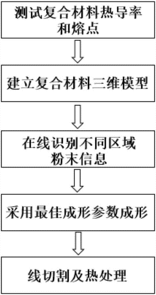
[0018] A composite material 3D printing forming method, comprising the following steps:

[0019] (1), respectively carry out the test of thermal conductivity, melting point to Fe and C in Fe / C composite material, and input the test result in the computer database of 3D printing equipment, described Fe powder and C powder are spherical or Nearly spherical, the average particle size of both is distributed between 20-45μm and the oxygen content is lower than 1000ppm;

[0020] (2), design the three-dimensional model of the composite material part by CAD software, then convert the three-dimensional model of the part into an STL file format and import it into the computer of the 3D printing device;

[0021] (3) Spread the Fe powder and C powder evenly on the powder bed according to the ratio requirements of the composite material, turn on the infrared detector, identify the material components in different regions of the composite material online, and feed back the recognition resul...

Embodiment 2

[0027] A composite material 3D printing forming method, comprising the following steps:

[0028] (1), respectively carry out the test of thermal conductivity, melting point to W and Cu in W / Cu composite material, and input the test result in the computer database of 3D printing equipment, described W powder and Cu powder are spherical or Nearly spherical, the average particle size of both is distributed between 20-45μm and the oxygen content is lower than 1000ppm;

[0029] (2), design the three-dimensional model of the composite material part by CAD software, then convert the three-dimensional model of the part into an STL file format and import it into the computer of the 3D printing device;

[0030] (3) Spread the W powder and Cu powder evenly on the powder bed according to the ratio of the composite material, turn on the infrared detector, identify the material components in different regions of the composite material online, and feed back the recognition results to the com...

Embodiment 3

[0036] A composite material 3D printing forming method, comprising the following steps:

[0037] (1), carry out the test of thermal conductivity, melting point to Al and SiC in Al / SiC composite material respectively, and input the test result in the computer database of 3D printing equipment, described Al powder and SiC powder are spherical or Nearly spherical, the average particle size of both is distributed between 20-45μm and the oxygen content is lower than 1000ppm;

[0038] (2), design the three-dimensional model of the composite material part by CAD software, then convert the three-dimensional model of the part into an STL file format and import it into the computer of the 3D printing device;

[0039] (3) Spread the Al powder and SiC powder evenly on the powder bed according to the ratio requirements of the composite material, turn on the infrared detector, identify the material components in different regions of the composite material online, and feed back the recogniti...


PUM


Abstract

The invention relates to a 3D printing forming method of a composite material. Before 3D printing forming, the heat conductivity and melting points of various base body materials forming the compositematerial are tested, and obtained data are input into a computer; then a recognizing detection device is used for regionally recognizing materials in different properties in the composite material; according to data of the recognized powder materials in different regions, a laser device is instructed to adjust process parameters in real time to perform printing; and in the whole printing process,the process parameters are adjusted and optimized along with changing of block information of powder, high quality forming of a composite material part of a composite structure is achieved, and the printing efficiency is improved.

Description

technical field [0001] The invention relates to the technical field of composite material manufacturing, in particular to a composite material 3D printing forming method. Background technique [0002] Composite materials are materials with new properties composed of two or more materials with different properties through physical or chemical methods on a macro scale. Due to their superior performance, composite materials are widely used in aerospace, military, automotive and other fields. Being more and more widely used, composite materials can be divided into fiber-reinforced composite materials, sandwich composite materials, fine-grained composite materials and hybrid composite materials according to their structural characteristics, and can be divided into resin-based, metal-based and ceramic-based materials according to different matrix materials. Composite materials, etc. [0003] According to the different matrix materials, the forming methods of composite materials a...

Claims


Application Information

Patent Timeline
Patent Type & Authority Applications(China)
IPC IPC(8): B22F3/105B33Y10/00B33Y50/02
CPCB33Y10/00B33Y50/02B22F10/00B22F10/32B22F10/66B22F12/41B22F12/90B22F10/36B22F10/28B22F10/64Y02P10/25
Inventor 周燕吴和保曾雄杨洲李秀朱小帅
Owner WUHAN INSTITUTE OF TECHNOLOGY
Learn More