
An automatic feeding system for precision components

A technology of automatic feeding and components, applied in the direction of conveyor objects, transportation and packaging, conveyors, etc., can solve the problem of damage to precision components, and achieve the effect of reducing friction, reducing the difficulty of fixing, and fixing firmly

Active Publication Date: 2021-01-22
HUIZHOU JUNYA DIGITAL TECH CO LTD
View PDF6 Cites 0 Cited by
  • Summary
  • Abstract
  • Description
  • Claims
  • Application Information

AI Technical Summary

Problems solved by technology

[0002] Precision components are generally used in special use scenarios. Usually, there are higher requirements for product quality, materials and process standards. The material, manufacturing process and execution standards of precision components are stricter than ordinary components. Therefore, The automatic feeding system of the prior art is generally used for the automatic feeding of ordinary components. The automatic feeding system of the prior art is easy to damage the precision components during the feeding process. Therefore, there is an urgent need for a method to prevent precision components from Automatic feeding system for precision components with surface wear

Method used


Image

  • An automatic feeding system for precision components
  • An automatic feeding system for precision components
  • An automatic feeding system for precision components

Examples


Embodiment 1

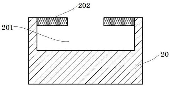
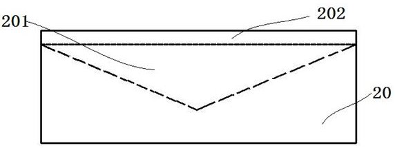
[0032] Such as figure 1 and figure 2 As shown, this embodiment provides an automatic feeding system for precision components, including: a hopper 10: the hopper is provided with a discharge port 101; a feeding assembly: including a base 20 and a conveyor belt 30, the base 20 is fixedly connected to the conveyor belt 30, and the base The upper surface of the 20 is provided with a slot 201, the slot 201 is opened along the lateral direction of the base 20 and runs through both ends of the base 20, the inner wall of the slot 201 is fixedly provided with a group of elastic clips 202 arranged along the lateral direction of the base 20, the elastic clips 202 The group includes two elastic clips 202 parallel to each other, the two elastic clips 202 are respectively fixed on the two opposite inner walls of the slot 201, and there is a gap between the two elastic clips 202; the manipulator 40: located at the discharge port Between 101 and the feeding component, it is used to clamp th...

Embodiment 2

[0035] Such as image 3 As shown, this embodiment provides an automatic feeding system for precision components, including: a hopper 10: the hopper is provided with a discharge port 101; a feeding assembly: including a base 20 and a conveyor belt 30, the base 20 is fixedly connected to the conveyor belt 30, and the base The upper surface of the 20 is provided with a slot 201, the slot 201 is opened along the lateral direction of the base 20 and runs through both ends of the base 20, the inner wall of the slot 201 is fixedly provided with a group of elastic clips 202 arranged along the lateral direction of the base 20, the elastic clips 202 The group includes two elastic clips 202 parallel to each other, the two elastic clips 202 are respectively fixed on the two opposite inner walls of the slot 201, and there is a gap between the two elastic clips 202; the manipulator 40: located at the discharge port Between 101 and the feeding component, it is used to clamp the precision com...

Embodiment 3

[0038] This embodiment provides an automatic feeding system for precision components, including: a hopper 10: the hopper is provided with a discharge port 101; a feeding assembly: including a base 20 and a conveyor belt 30, the base 20 is fixedly connected to the conveyor belt 30, and the upper surface of the base 20 A slot 201 is provided. The slot 201 is opened along the transverse direction of the base 20 and runs through both ends of the base 20. The inner wall of the slot 201 is fixedly provided with a group of elastic clips 202 arranged along the lateral direction of the base 20. The group of elastic clips 202 includes two Two elastic clips 202 parallel to each other, the two elastic clips 202 are respectively fixed on two opposite inner walls of the slot 201, there is a gap between the two elastic clips 202; manipulator 40: located between the discharge port 101 and the inlet Between the material components, it is used to clamp the precision components in the hopper 10, ...


PUM


Abstract

The invention provides a precision component automatic feeding system. The precision component automatic feeding system comprises a hopper, a feeding assembly, a manipulator and a control assembly. The hopper is provided with a discharging port, the feeding assembly comprises a base and a conveying belt, the base is fixedly connected to the conveying belt, a slot is formed in the upper surface ofthe base, the slot is formed in the transverse direction of the base, and penetrates through the two ends of the base, and an elastic clamping strip set arranged in the transverse direction of the base is fixedly arranged on the inner wall of the slot; the elastic clamping strip set comprises two mutually parallel elastic clamping strips which are fixed to the two opposite inner walls of the slotcorrespondingly, and a gap is left between the two elastic clamping strips; and the manipulator is arranged between the discharging port and the feeding assembly to be used for clamping a precision component in the hopper and enabling the precision component to be clamped to the interior of the slot from the side face, and the control assembly is used for controlling the manipulator to clamp and place the precision component and controlling the conveying belt to convey the precision component. According to the precision component automatic feeding system, the precision component can be effectively prevented from being scratched.

Description

technical field [0001] The invention relates to a feeding system, in particular to an automatic feeding system for precision components. Background technique [0002] Precision components are generally used in special use scenarios. Usually, there are higher requirements for product quality, materials and process standards. The material, manufacturing process and execution standards of precision components are stricter than ordinary components. Therefore, The automatic feeding system of the prior art is generally used for the automatic feeding of ordinary components. The automatic feeding system of the prior art is easy to damage the precision components during the feeding process. Therefore, there is an urgent need for a method to prevent precision components from Automatic feeding system for precision components with surface wear. Contents of the invention [0003] In view of this, the present invention provides an automatic feeding system for precision components that ...

Claims


Application Information

Patent Timeline
Patent Type & Authority Patents(China)
IPC IPC(8): B65G47/90
CPCB65G47/90B65G2201/0214
Inventor 邹乾坤樊领刘继承
Owner HUIZHOU JUNYA DIGITAL TECH CO LTD
Learn More