Refrigerant heating device and air conditioner

A heating device and refrigerant technology, applied in refrigeration and liquefaction, lighting and heating equipment, refrigerators, etc., can solve the problems of reducing the service life of air conditioners and system blockage, and achieve the effects of preventing system blockage, preventing local overheating, and avoiding leakage

Pending Publication Date: 2018-05-04
GREE ELECTRIC APPLIANCES INC +1
View PDF6 Cites 0 Cited by
  • Summary
  • Abstract
  • Description
  • Claims
  • Application Information

AI Technical Summary

Problems solved by technology

[0006] Therefore, the technical problem to be solved by the present invention is to overcome the defect that the local overheating of the refrigerant heating device in the prior art will easily cause the decomposition and coking of the lubricating oil to cause system blockage and reduce the service life of the air conditioner, thereby providing a refrigerant heating device and air conditioner

Method used


Image

  • Refrigerant heating device and air conditioner
  • Refrigerant heating device and air conditioner
  • Refrigerant heating device and air conditioner

Examples


Embodiment 1

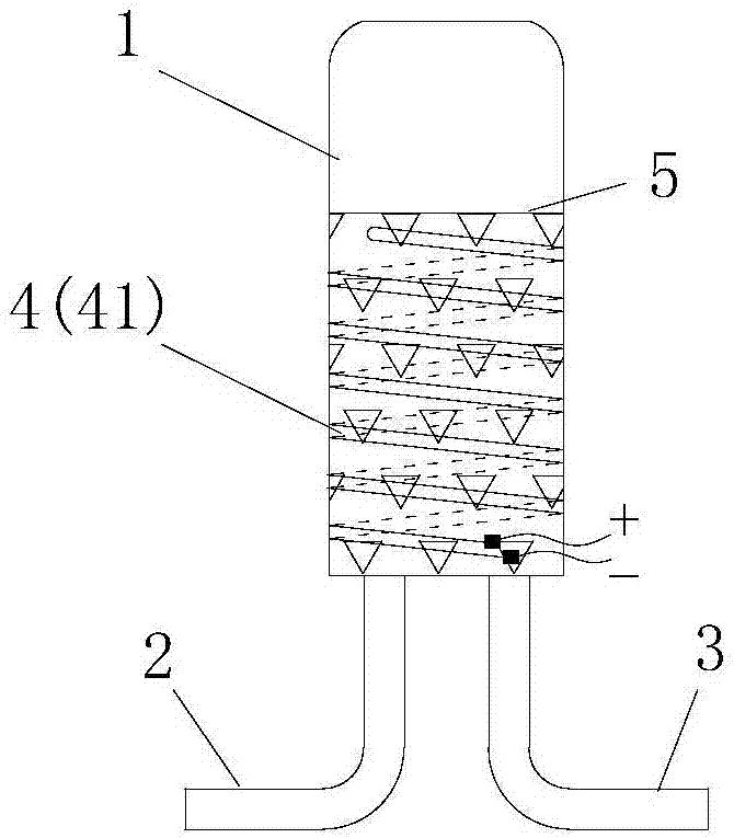
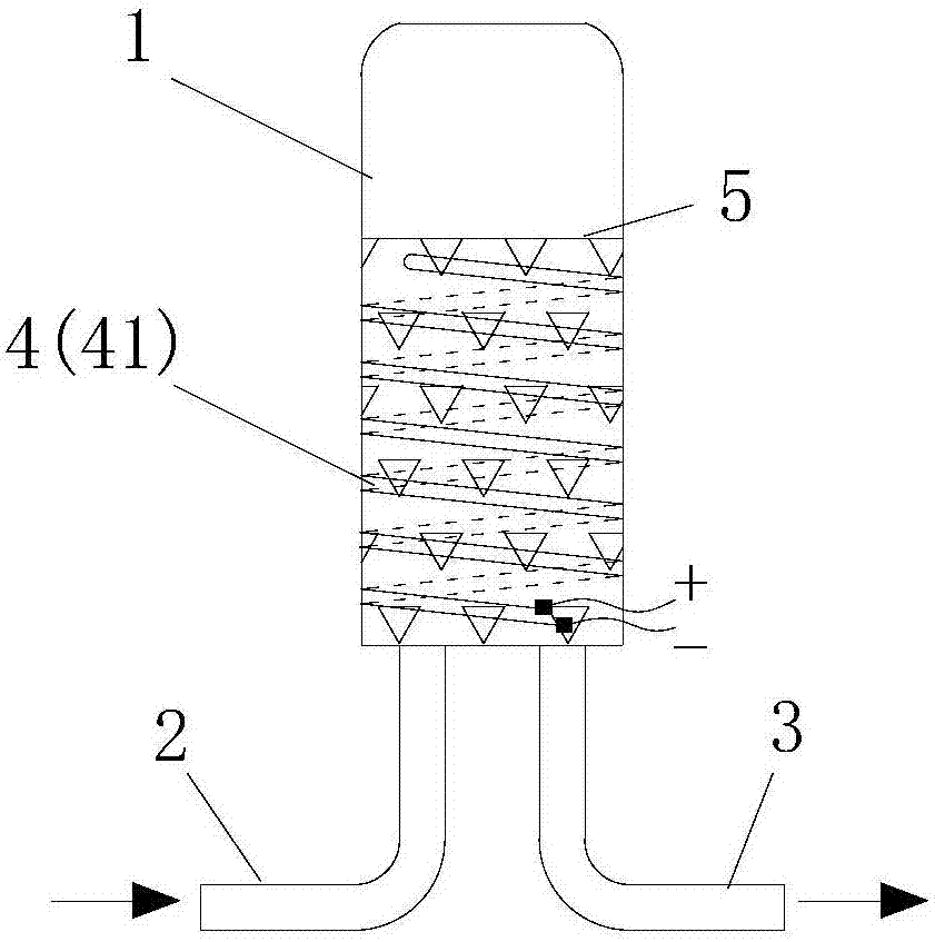
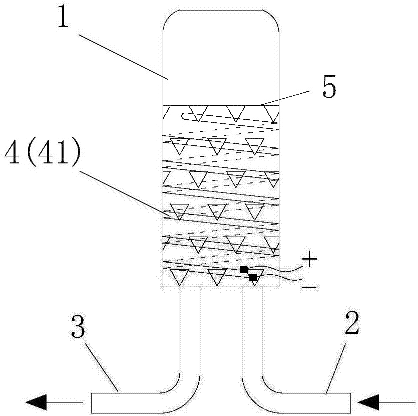
[0073] In this embodiment, there are two inlet and outlet pipes (lower left end and lower right end), all of which are arranged at the bottom of the liquid storage tank (such as figure 1 shown); during heating or defrosting, the refrigerant flows in from the lower left end and flows out from the lower right end (such as figure 2 shown); during refrigeration, the refrigerant flows in from the lower right end and flows out from the lower left end (such as image 3 shown).

Embodiment 2

[0075] In this embodiment, there are three inlet and outlet pipes (lower left end, lower right end and upper end), wherein the lower left end and the lower right end are arranged on the bottom of the liquid storage tank, and the upper end is arranged on the top of the liquid storage tank (such as Figure 4 shown); during heating, the refrigerant flows in from the lower left end and flows out from the lower right end (such as Figure 5 shown); during defrosting, the refrigerant flows in from the lower left end and flows out from the upper end (such as Figure 6 shown); during refrigeration, the refrigerant flows in from the lower right end and flows out from the lower left end (such as Figure 7 shown). During heating (when the device is powered on) or during defrosting, the refrigerant can also flow in from the lower left end and flow out from the lower right end and upper end simultaneously.

[0076] Preferably,

[0077] The outer surface of the liquid storage tank 1 is at...


PUM


Abstract

The invention provides a refrigerant heating device and an air conditioner. The refrigerant heating device comprises a liquid storage tank (1), an inlet pipe (2), an outlet pipe (3) and a heating component (4), wherein the liquid storage tank (1) is arranged in a vertical direction; the inlet pipe (2) is connected with the liquid storage tank (1) and communicates with the interior of the liquid storage tank (1), and refrigerant can be introduced into the liquid storage tank (1) through the inlet pipe (2); the outlet pipe (3) is connected with the liquid storage tank (1) and communicates with the interior of the liquid storage tank (1), and the refrigerant in the liquid storage tank (1) can be output through the outlet pipe (3); and the heating component (4) is arranged on the liquid storage tank (1) and is located in a position of the vertical lower part of the liquid storage tank (1). By adopting the refrigerant heating device, local overheating generated by overtemperature of gaseousrefrigerant which is heated can be prevented and avoided, the conditions of system blockage caused by decomposition and coking of lubricating oil and short service life of the air conditioner are prevented, the uniform heating degree of the refrigerant is increased, and the service life of the air conditioner is prolonged.

Description

technical field [0001] The invention belongs to the technical field of air conditioning, and in particular relates to a refrigerant heating device and an air conditioner. Background technique [0002] The defrosting heat of the existing heat pump air-conditioning system mainly comes from the work done by the compressor. If the indoor fan is running during the defrosting period, the defrosting heat will be blown into the room for heating, thereby weakening the defrosting ability. [0003] In order to solve this problem, the patent application number CN201210115635.7 discloses a refrigerant heating device. The device is composed of a shell, an electric heating tube and a refrigerant inlet pipeline; the shell is provided with a refrigerant inlet, a refrigerant outlet, and an electric heating tube installation port; the electric heating tube extends into the inner cavity of the shell through the electric heating tube installation port , The power terminal of the electric heatin...

Claims


Application Information

Patent Timeline
Patent Type & Authority Applications(China)
IPC IPC(8): F25B47/00
CPCF25B47/00
Inventor 彭光前于博车雯陈英强李啸宇翟振坤连彩云吴俊鸿廖敏
Owner GREE ELECTRIC APPLIANCES INC
Why Eureka
Try Eureka