Vehicle-mounted head-up display system having error correction function
A head-up display system, error calibration technology, applied in optical components, optics, instruments, etc., can solve problems such as affecting the viewing of HUD information, unable to obtain driving information, etc., to achieve a wide range of applications, thin and light, and increase the effect of strength.
- Summary
- Abstract
- Description
- Claims
- Application Information
AI Technical Summary
Problems solved by technology
Method used
Image
Examples
Embodiment 1
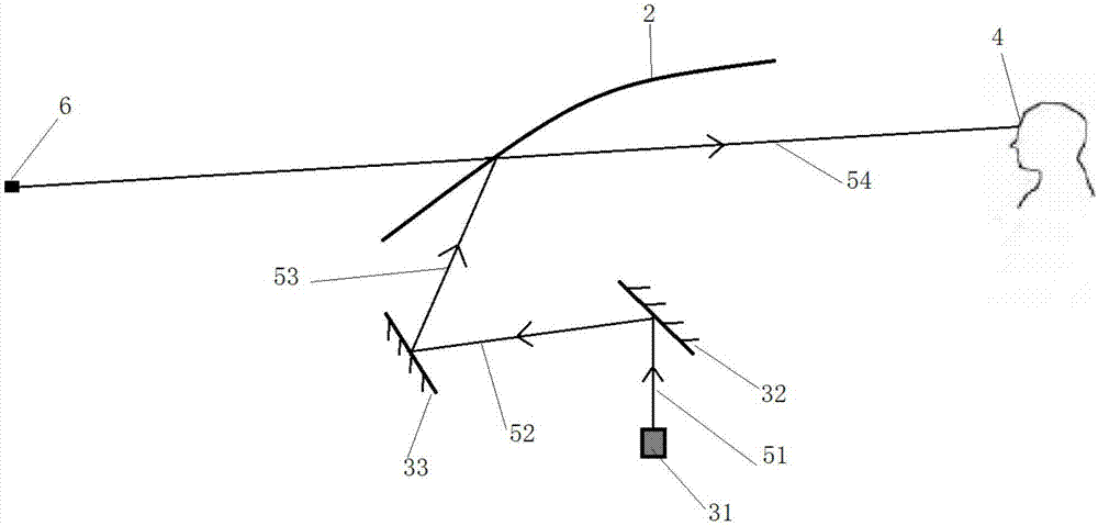
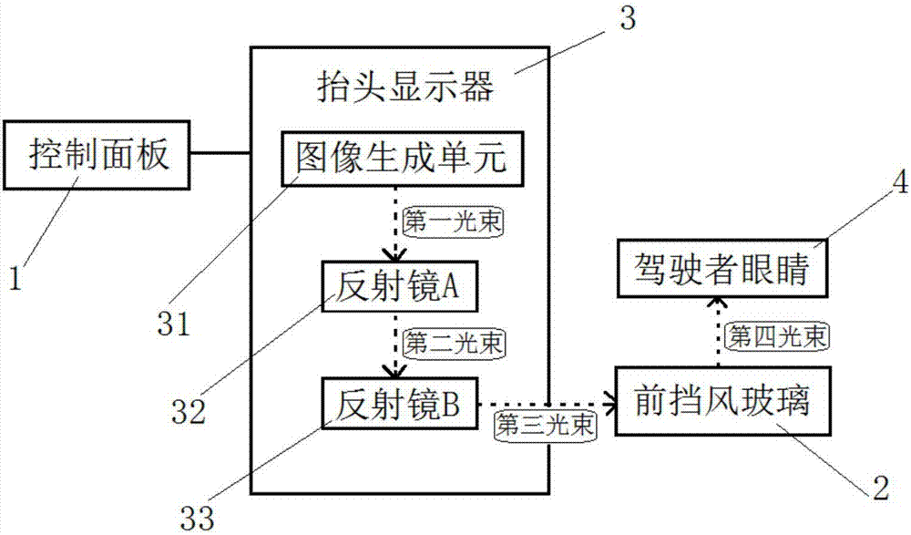
[0027] see figure 1 with figure 2 As shown, it is the optical path diagram and structural block diagram of the vehicle-mounted head-up display system with error calibration function of the present invention.
[0028] Such as figure 1 with figure 2 As shown, a vehicle-mounted head-up display system includes a control panel 1, a front windshield 2 and a head-up display 3 arranged in front of the front windshield 2, and the head-up display 3 includes an image generating unit 31 and several reflectors Mirror, the control panel 1 is connected with the image generation unit 31 for controlling the display image of the image generation unit 31, the display image forms a light beam, and is projected on the front windshield 2 after being reflected by the reflector , so that the driver observes the virtual image 6 of the displayed image.
[0029] Wherein, the head-up display 3 is installed on the vehicle instrument panel between the driving position and the front windshield 2; the ...
Embodiment 2
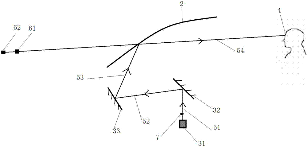
[0035]As described above, the vehicle-mounted head-up display system differs from this embodiment in that, as image 3 As shown, it is the optical path diagram of the vehicle-mounted head-up display system in this embodiment. A transmissive optical element 7 is arranged between the image generating unit 31 and the reflector, and the transmissive optical element 7 is arranged on the beam path of the first beam 51. , and only a part of the first light beam 51 is projected onto the mirror A 32 after passing through the transmissive optical element 7, and the rest of the first light beam 51 is emitted from the imaging production unit 31 and directly projected onto the mirror A 32, the transmissive optical element 7 is used to change the route of the light beam, so that the first light beam 51 is divided into two light beams and projected on the mirror A 32, and finally the display image sent by the same image generating unit 31 can present Two virtual images at different distances...
Embodiment 3
[0038] As described above, the vehicle-mounted head-up display system differs from this embodiment in that, as Figure 4 As shown, it is a diagram of the distribution area of the display image of the vehicle-mounted head-up display system in this embodiment. The display image on the image generation unit 31 is divided into a main display area 311 and an auxiliary display area 312. The main display area 311 is generally Located in the middle of the image generating unit 31 or occupying most of the image generating unit 31 , the auxiliary display area 312 is located at the edge of the image generating unit 31 .
[0039] The content of the main display area 311 includes navigation information, ADAS, ACC, blind spot detection, obstacle recognition, lane warning warning (LDW), AR-HUD and other information combined with actual traffic conditions, thereby enhancing the driver's understanding of the actual driving environment. Perception; the content of the auxiliary display area 31...
PUM
 Abstract
Description
Claims
Application Information
 - R&D
- Intellectual Property
- Life Sciences
- Materials
- Tech Scout
- Unparalleled Data Quality
- Higher Quality Content
- 60% Fewer Hallucinations
Browse by: Latest US Patents, China's latest patents, Technical Efficacy Thesaurus, Application Domain, Technology Topic, Popular Technical Reports.
© 2025 PatSnap. All rights reserved.Legal|Privacy policy|Modern Slavery Act Transparency Statement|Sitemap|About US| Contact US: help@patsnap.com


