A computer interlocking system and its redundancy switching method

A computer interlocking and redundant switching technology, applied in the field of rail transit, can solve the problems of reduced production efficiency, high development difficulty, and high requirements for debugging and maintenance, and achieves the goal of improving production efficiency, reducing development difficulty, and reducing debugging and maintenance. Effect

Active Publication Date: 2020-12-29
CRSC RESEARCH & DESIGN INSTITUTE GROUP CO LTD
View PDF7 Cites 0 Cited by
  • Summary
  • Abstract
  • Description
  • Claims
  • Application Information

AI Technical Summary

Problems solved by technology

However, the development of this redundant method is difficult, and the requirements for debugging and maintenance are relatively high, which greatly reduces production efficiency.

Method used


Image

  • A computer interlocking system and its redundancy switching method
  • A computer interlocking system and its redundancy switching method
  • A computer interlocking system and its redundancy switching method

Examples


Embodiment Construction

[0037] The present invention is described below based on examples, but the present invention is not limited to these examples.

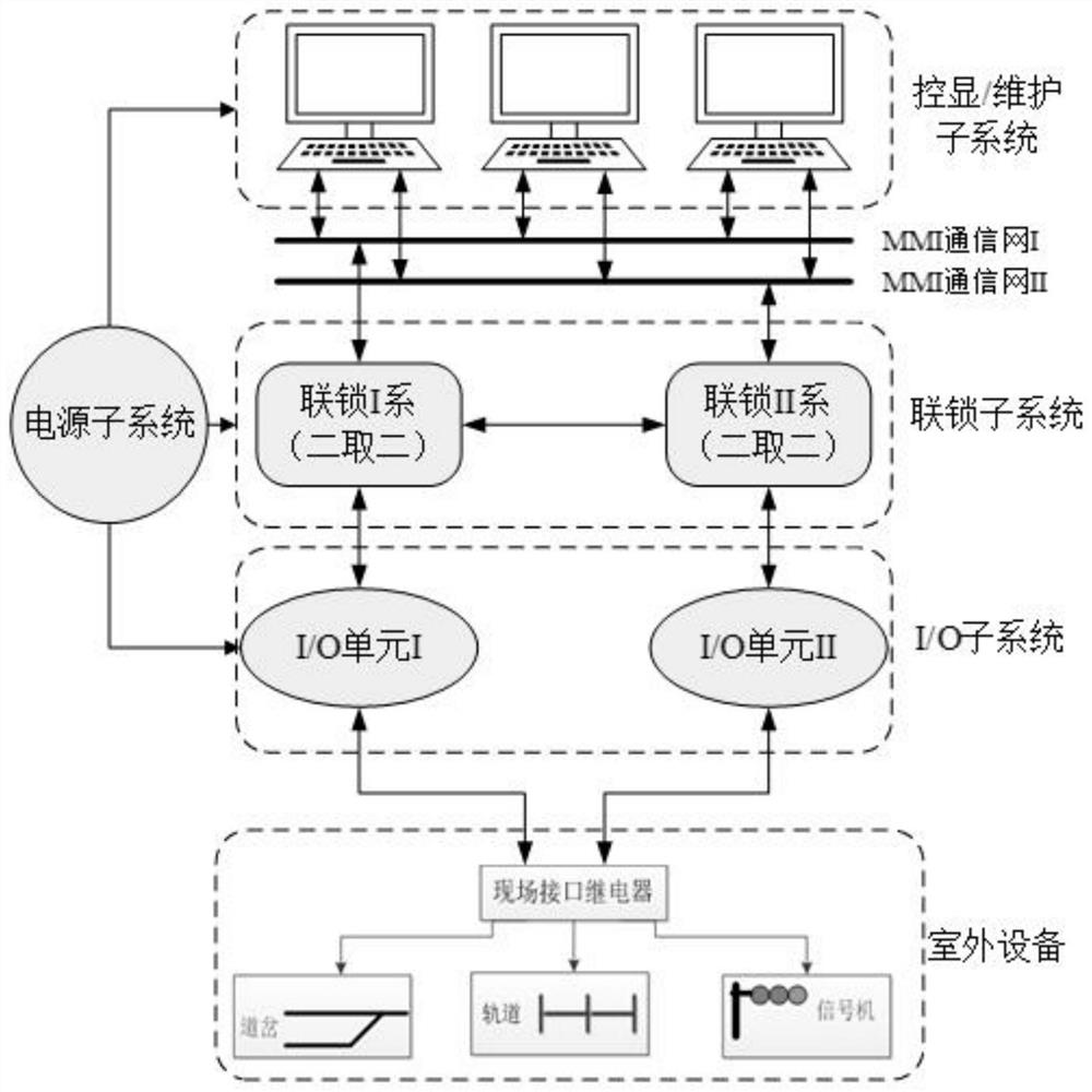
[0038] A computer interlocking system provided by the invention is a signal system for realizing station interlocking with a computer as the main technical means. The computer interlocking system forms an interlocking relationship that is both interconnected and mutually restricted by all relatively independent signal equipment included in the interlocking signal machine, track circuit, and turnout in the station and the section, and performs centralized control to ensure traffic Safe control system.

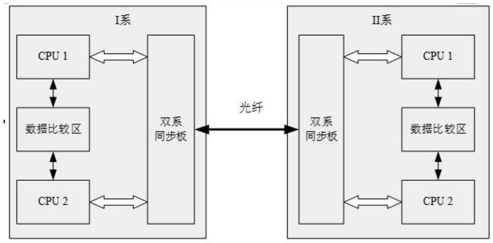
[0039] Such as figure 1 As shown, the computer interlocking system provided by the present invention includes: power supply subsystem, interlocking subsystem, IO subsystem (input and output subsystem), control display and maintenance subsystem. Among them, the power supply subsystem provides the required power supply for the equipment of all subsyste...


PUM


Abstract

The invention provides a computer interlocking system and its redundant switching method, including an interlocking subsystem, the interlocking subsystem includes the same and interconnected interlocking I system and interlocking II system, wherein: the interlocking I system and the interlocking system Both the II series include two CPUs with the same hardware and using task-level synchronization, and the two CPUs respectively run executable files generated by compiling the same program code with different compilers. The invention adopts heterogeneous software / hardware and fixed difference program starting time to reduce the probability of common mode failures, reduces the difficulty of development while reducing common mode failures, improves production efficiency, and reduces debugging and maintenance. requirements.

Description

technical field [0001] The invention relates to the field of rail transit, in particular to a computer interlocking system applied to rail transit stations. Background technique [0002] In the development of the existing rail transit interlocking platform, the interlocking architecture generally adopts a 2 by 2 out of 2 platform. It is composed of the same 2 out of 2 structure of the two series A and B. Each series of motherboards is equipped with two CPUs (central processing units) with identical hardware, and a set of common software is run inside. Under normal circumstances, one system is the logical master, and the other is the logical backup. The two CPUs of each system adopt clock-level synchronization, and automatically switch to the backup system when the main system fails. However, due to the use of clock-level synchronization, it is directly subject to the main processing frequency of the CPU, that is, the CPU clock frequency cannot be too fast, otherwise the dat...

Claims


Application Information

Patent Timeline
Patent Type & Authority Patents(China)
IPC IPC(8): G06F11/20G06F11/16
CPCG06F11/1629G06F11/202G06F11/1487G06F11/2038G06F11/2028G06F11/165B61L19/06B61L2019/065B61L27/30
Inventor 刘晓冬刘贞敖奇张利峰赵雪江叶峰张夫松陈代英邹未栋吕媛媛
Owner CRSC RESEARCH & DESIGN INSTITUTE GROUP CO LTD
Why Eureka
Try Eureka