Push-pull switching power supply topological structure

A technology of switching power supply and topology structure, which is applied in the direction of electrical components, adjusting electric variables, instruments, etc., and can solve problems such as consumption and large resistance heat

Inactive Publication Date: 2018-05-04
BEIJING UNIV OF TECH
View PDF2 Cites 3 Cited by
  • Summary
  • Abstract
  • Description
  • Claims
  • Application Information

AI Technical Summary

Problems solved by technology

However, the principle of the commonly used passive buffer network is mostly to use resistance to consume the energy of the leakage inductance, which will generate a lot of resistance heat in a short time, and there are certain requirements for the power of the resistance

Method used


Image

  • Push-pull switching power supply topological structure
  • Push-pull switching power supply topological structure
  • Push-pull switching power supply topological structure

Examples


Embodiment Construction

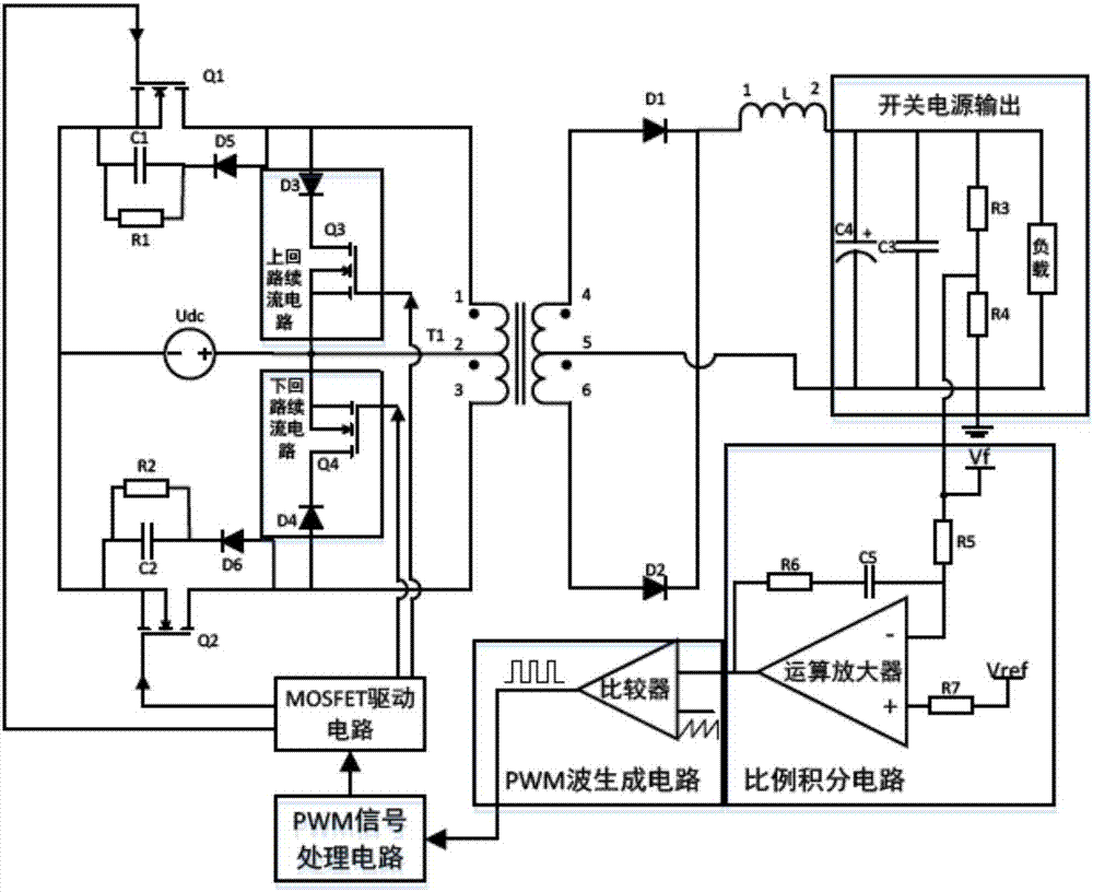
[0018] Combine below image 3 A specific embodiment of the present invention is described:

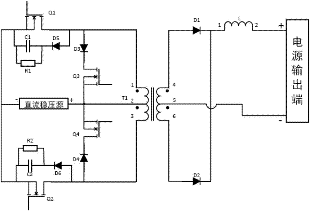
[0019] image 3 It is a voltage-type output switching power supply adopting the push-pull topological structure described in the present invention. Including power main circuit, upper loop freewheeling circuit, lower loop freewheeling circuit, switching power supply output, proportional integral circuit, PWM wave generating circuit, PWM signal processing circuit, MOSFET drive circuit.

[0020] The main circuit part includes a DC stabilized voltage source, MOSFET tube Q1, MOSFET tube Q2, transformer T1, diode D1, diode D2, filter inductor L, and the primary side and secondary side of the transformer T1 each have a center tap. The connection relationship between them is: the center tap of the primary side of T1 is connected to the positive pole of the DC voltage stabilizer; the first terminal of the primary side of T1 is connected to the drain of Q1, and the source of Q1 is connected t...


PUM


Abstract

The invention provides a push-pull switching power supply topological structure. The problem that energy of magnetic inductance in a transformer must be maintained on a secondary side when a traditional push-pull switching power supply is in dead time is solved. To maintain the energy of the magnetic inductance, a follow current conduction circuit must be formed on the secondary side of the transformer. For a push-pull circuit, two rectifier diodes are usually used to achieve the purpose, but the premise to ensure the reliable conduction of the diodes is that a load large enough must be available to generate a forward current that can be sufficiently reliably conducted. In addition, in an instant when an inverter switch tube of the push-pull circuit, a very high voltage spike is generateddue to the leakage inductance of the transformer, and a switching tube buffer circuit is usually used to solve the problem. According to the push-pull switching power supply topological structure, a magnetic inductance magnetic inductance circuit is added on a primary side, to maintain the energy of the magnetic inductance on the primary side, so that the voltage spike can be generated in an instant of switching tube turn-off, and the burden on the buffer circuit is reduced.

Description

technical field [0001] The invention belongs to the technical field of power electronics, and in particular relates to a topological structure of a push-pull switching power supply circuit. Background technique [0002] In the field of inverters, especially automotive inverters, due to its simple circuit, fewer power tubes, and less PCB space, push-pull circuit applications are widely used. But the push-pull selected power tube requires twice the input voltage characteristics, which is perfect for low-voltage and high-current point circuits, and has become the first choice for inverter power supply engineers. In the push-pull circuit, there is a center tap on the primary side of the transformer. The center tap is connected to the DC voltage source, and forms two sets of circuits with the two switch tubes respectively. By controlling the switch tubes to conduct alternately, the voltage of the DC voltage source can be adjusted. Inversion to produce an alternating positive and...

Claims


Application Information

Patent Timeline
Patent Type & Authority Applications(China)
IPC IPC(8): H02M3/337H02M1/34
CPCH02M1/34H02M3/3378H02M1/348
Inventor 黄鹏飞朱大芹胡伊通何超李滨瞿莹
Owner BEIJING UNIV OF TECH
Why Eureka
Try Eureka